
How to make a homemade antenna for the basement. Simple DIY antenna for digital television DVB-T2
Despite the huge number of television antennas presented on the consumer market, which can be easily purchased at any electronics store, interest in how to make an antenna for a TV with your own hands does not disappear. This interest can be explained by a reluctance to spend money on buying an antenna, being away from retail outlets (if you are in the outback or at the dacha) or the failure of the purchased one.
Antennas for a television receiver can be divided into several types.
- All-wave antenna– the design is easy to manufacture; it can be made from simple available materials. It picks up a digital signal quite well outside the city, where there is not much interference. When located near a broadcast tower, it can receive analog television.
- Log-periodic band antenna also easy to make. It has perfect consistency with the feeder across all ranges, without changing its parameters. Since this design has average technical parameters, it can be used in the country, or as an indoor antenna in the city.
- UHF antenna. A simplified modification of the Z-antenna is often used; it works well, regardless of the signal reception conditions.
All-wave antenna
All-wave TV signal catchers are also called frequency independent (FIN). Their designs can be different.
Of two petals
The figure shows an all-wave antenna made from two metal plates triangular in shape and two wooden slats on which copper wire is stretched in the shape of a fan.
Copper wire can be taken of any diameter, it does not play a special role. The ends of the wire are attached at a distance of 20 to 30 mm from each other. The plates with the other ends of the wire soldered together should be located at a distance of 10 mm from each other.
The metal plate can be replaced with a square piece of fiberglass, which has copper foil on one side.
Since the design of the homemade antenna is square in shape, its height will be equal to its width, and the angle between the panels will be 90 degrees. Zero potential point marked in yellow in the figure. There is no need to solder the cable braid in this place - tying it tightly will be enough.
A television signal receiver assembled in this way in the form of two lobes is capable of receiving both all decimeter channels and meter ones. Moreover, it picks up signals well in all directions. But if you install the CNA in an area of poor signal reception from a TV tower, it will only work normally with amplifier. Others can also be used.
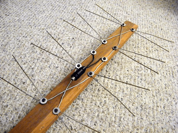
Butterfly shaped
You can make a television antenna in the shape of a butterfly with your own hands. To make this fairly powerful antenna yourself, you need to prepare a board or plywood with dimensions of 550 x 70 x 5 mm, a wire with a copper core with a cross-section of 4 mm, and, accordingly, a PK75 cable.
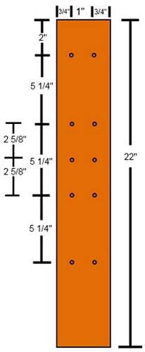
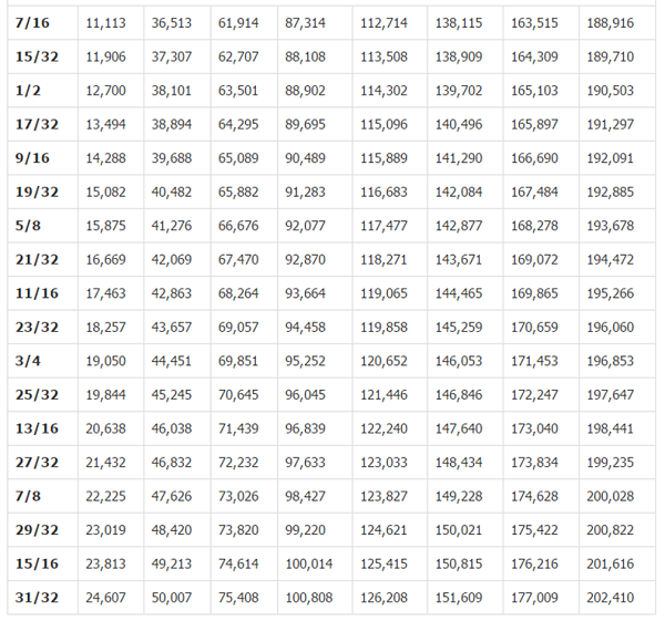
- Mark the holes on the plywood and drill them. Dimensions in the picture are in inches. Below the figure is a table for converting inches to mm.

- From copper wire you need to cut 8 pieces of the same length, 37.5 cm each.
- In the center of each wire, clear sections of insulation (2 cm each), as in the figure.

- After this, you should cut off 2 more pieces of wire, already 22 centimeters each, divide them into 3 equal parts and remove the insulation at the separation points.
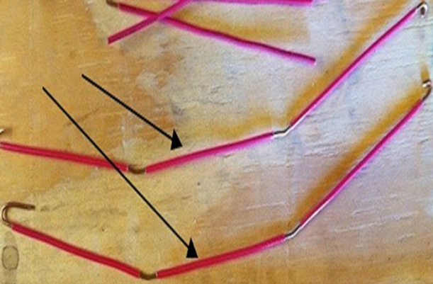
- Give the segments V-shape. You should be careful to maintain a distance of 7.5 cm between the ends of the wire. This is the optimal distance to receive a clear signal.
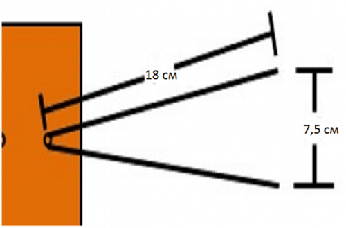
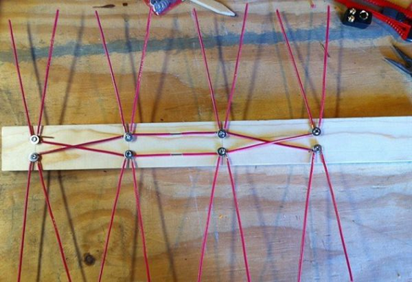
- Connect all the elements according to the figure below.
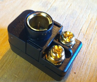
- Next, you need to purchase a socket to connect the plug to it.
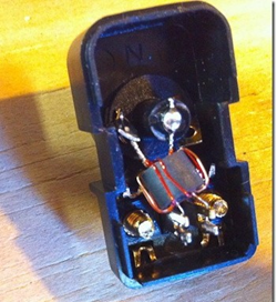
- The cable must be soldered to the coil contacts, as in the figure.
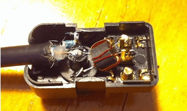
- Make 2 more pieces of wire of the required length to connect the antennae to the socket.
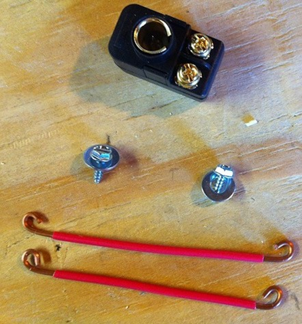
- Screw the socket onto the board and connect all the elements.

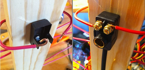
That's all - you have made an antenna for your TV with your own hands.
From beer cans
To make such an original ChNA you will need 2 cans (0.5 l or 0.75) of beer or other drink. But before you make a television antenna, you need to consider some material requirements. Namely, it is recommended to purchase a high-quality television cable with a resistance of 75 ohms per meter. Which is correct? Make sure that the central core is strong and that the braid is double and continuous.
Don’t forget, the longer the cable, the stronger the signal attenuation will be, which is especially important for receiving meter waves, in contrast to UHF, for which the length of the wire also matters, but not so much.
It will also be necessary to prepare the usual wooden trempel, a couple of self-tapping screws, electrical tape or tape and, if possible, a soldering iron with tin.
An antenna made from beer cans can receive both the UHF and meter wavelengths.
To illustrate the entire process, you can watch the video.
Log-periodic antenna
A log-periodic antenna (LPA) can be used to receive radio waves in both the meter and decimeter ranges. To make such a signal receiver, you can use an aluminum tube with a diameter of 10 mm and metal rods (studs) as a stand, which can be purchased at a store that sells fasteners. Ideally, instead of threaded rods, it is better to use smooth tubes or rods. A plastic U-shaped box is used as a base.
When the soldering is completed, the manufacture of the device can be considered complete and you can begin testing your creation.
UHF antenna
Homemade decimeter signal catchers can have different shapes and designs, from the simplest to manufacture to more complex devices.
Ring-shaped
The simplest design for receiving UHF can be made in a short time with your own hands from scrap materials. All you need is a coaxial cable and a piece of plywood of the appropriate size.

Now all this needs to be assembled:
- prepare a piece of coaxial cable (RK75) 530 mm long (a ring will be made from it);
- also cut another piece of cable 175 mm long - this will be a loop;
- make a ring (1), solder a loop (2) and a cable (3) to it, which connects to the TV;
- secure it all to a plywood sheet and point the completed TV signal receiver towards the TV tower.
If your TV receiver uses such an antenna, try making a more complex device.
Figure 8
You can make your own home UHF antenna from wire in the shape of the number 8. To make such a receiver, you can use copper or aluminum wire with a diameter of 3 to 5 mm, as well as PK75 cable. During the manufacturing process you will also need glue gun

Manufacturing progress.
- Using wire cutters, you need to cut 2 pieces of wire 56 cm each.
- At the ends of each segment, make a loop, which should take 1 cm.
- Bend the wire squares and connect the loops. Solder the cable to the squares as shown in the picture. The central core is soldered to one square, and the braid to the other. The distance between the elements should be 2 cm. The entire structure can be secured in the lid of a 20 liter water bottle, filled with glue.


Such a UHF receiver can be placed anywhere, and it does not require an amplifier. Perhaps an amplifier may be needed if the device is outdoors and the cable length is significant. In this case, to compensate for signal losses, its installation will be required.
From a metal-plastic pipe
You can make a television antenna with your own hands from an ordinary metal-plastic pipe. This will result in a device for receiving UHF with a possible range from 480 MHz to 1000 MHz. This “model” uses a pipe with a diameter of 16 mm and a cable of 5.5 m. The ring will require 55 cm of pipe, and the stand will require 14 cm, which is equal to a quarter of the wavelength. This serves to better match the outer braiding of the cable and reduces high frequency currents.
The cable exit in this design is made through a hole in the pipe. The cable braid should be attached with a clamp to the stripped part of the pipe. The central core of the cable is attached to the ring (you can use a screw with a washer and a nut). This homemade product works well as an indoor antenna in apartments with reinforced concrete walls that do not transmit television waves well. Thanks to the extended cable, you can take it out onto the balcony or place it on the windowsill - the quality of reception will only improve.
In the form of a frame
Another UHF antenna design is assembled in the form of a frame. It will be made from aluminum plates(stripes).

Thus, home-made antennas will help you save money on purchasing them, and in some cases get out of the situation where you have a TV, but the standard antenna is out of order, or it doesn’t exist at all. Moreover, the quality of reception of homemade products is no worse than their factory counterparts. If you do not want to make the device yourself, then the information in the store will be useful to you.
Antenna is a radio device designed to receive and emit electromagnetic waves through the air.
If you live within direct visibility of a television tower, then a simple homemade indoor television antenna, the design of which is presented in this article, is quite suitable for receiving digital television. This antenna is designed to receive television broadcasts in the digital television frequency range (470–790 MHz).
The design of a television antenna is simple and does not require special knowledge to repeat. To make it you will need 70 cm of copper wire with a diameter of 2-3 mm, a piece of double-sided fiberglass sheet, 1.5 m of coaxial television cable with a characteristic impedance of 75 Ohms and an F-plug.
Instructions for making a UHF television antenna
The first thing you need to do is select a piece of copper wire with a diameter of 2-3 mm and a length of 70 cm. For these purposes, a single-core copper wire is well suited for laying electrical wiring. If there are several conductors in the cable, then you need to carefully cut off one conductor along the groove, being careful not to damage the insulation. It is not needed for the antenna to work; the insulation is left only for aesthetic appearance.
An aluminum wire will also work, but then it will have to be connected to the contacts of the matching transformer board using a threaded connection. Please note that the nut should not touch the shielding foil of the transformer; if it does, then you need to lay an insulating washer or trim the foil.

If you use a wire without insulation, you can put a vinyl chloride tube on it for beauty.

Next, the wire needs to be bent into a ring with a diameter of approximately 220 mm. High precision is not needed here. A paint bucket holder or any other round container of suitable size works well for this.
When the antenna ring is ready, you can begin manufacturing the printed circuit board for the matching transformer.

The printed circuit board is made of fiberglass or getinax, foil-coated on both sides, 1.5 mm thick, 25x30 mm in size. The photo shows the appearance of the transformer printed circuit board on both sides.

This photo shows a negative of the antenna circuit board. The width of the current-carrying tracks is 1 mm, the distance between the tracks is 1.5 mm. Antenna board size 25×30 mm.
If it is not possible to make a printed circuit board for the manufacture of an antenna using a chemical method, then it can be made mechanically. To do this, you need to remove unnecessary sections of the foil, leaving only the contact pads, and lay out the current-carrying paths from copper wire with a diameter of 0.3-0.5 mm, gluing it to the board, for example, with “Moment” glue.
To give an aesthetic appearance and increase the mechanical strength of the antenna, the transformer is placed in a plastic box in which holes for the ring and antenna cable are pre-drilled.

When all the parts are prepared, you can begin assembling the antenna. The ends of the ring, pre-tinned with solder, are inserted into the box and bent at a right angle at a distance of 3 mm. Next, the ends are inserted into the printed circuit board of the antenna transformer and soldered with solder using a soldering iron.

The antenna board is placed on the bottom of the box and secured with an M3 screw and nut.
You first need to install a television F-connector on one end of it, and cut the other one and solder its ends onto a printed circuit board. The center core of the cable is soldered directly to the right end of the ring, and the braided shielding is soldered directly to the foil of the antenna board.
For reliable operation of the antenna, you need to solder or attach the cable in the following order. First, the shielding braid is soldered, then you need to pull the cable well to remove the slack, and only then solder the central core. In this case, when moving the antenna to find a place in the room with the maximum signal level and stretch the cable, the central core will not break.

If the cable screen is made of aluminum foil, then it can be pressed to the foil of the board using a metal clamp placed on a screw and secured with a nut. The technology for attaching the screen with a clamp is discussed in the article “How to make a TV crab with your own hands.”
All that remains is to close the box with a lid, insert the connector into the TV and tune the channels to the desired programs. In order to ensure image quality with minimal noise, you need to move the antenna around the room to find a place with the maximum television signal.
How to replace the matching printed circuit board
cable loop
The use of a printed circuit board to match the antenna with a coaxial cable allows you to make the antenna more compact.

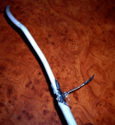
If there is no desire or opportunity to make a printed circuit board, then without losing the quality of the antenna’s performance, it can be replaced with a loop, which is also called a U-elbow, which is a section of television cable bent in half, connected to the antenna according to the circuit, as in the photograph below.

To make a matching loop, you need to take a piece of television cable 162 mm long, with which the antenna will be connected to the TV. Cut its ends and solder the central cores to the ends of the ring, the distance between which should be 60 mm. Next, the end of the cable going to the TV is cut and its central core is soldered to either end of the antenna ring, and the shielding wire is connected to the shielding wires of the loop, as shown in the photograph.
When soldering the shielding braid, care must be taken so that the insulation of the central core does not melt and the braid does not come into contact with it.
The photo shows the soldering of a cable to an antenna ring made of aluminum wire with a diameter of 3 mm. Since it is difficult to solder wires to aluminum with soft solder, the ends of the ring were slightly flattened, holes were drilled in them, and brass petals were secured with rivets. The central cores of the cable are soldered securely to the petals.
The indoor antenna allows you to receive terrestrial television, analogue and digital, at home. Analog television is gradually becoming a thing of the past, and digital television is becoming increasingly widespread.
Currently, there are two multiplexes with 10 channels each, work is underway to introduce a third multiplex with another 10 channels, some of them will be in HD quality. The first two multiplexes are free, but the third one may require a fee.
To connect to terrestrial digital television you will need:
- install a decimeter antenna, indoor or outdoor;
- purchase a special digital set-top box if your TV does not support receiving a DVB-T2 signal;
- connect the antenna and set-top box with a television cable.
Many companies provide services for connecting to terrestrial television. But it’s actually easy to make and set up an indoor antenna with your own hands. After that, you will be able to watch 20 channels in digital quality for free.
Different ways to make an antenna
You can make an indoor TV antenna with your own hands in different ways from different materials. First, make sure that your home is in a reliable reception area. This can be checked on the official website of digital terrestrial television. If you are far from the broadcast tower, then you will not be able to catch the signal with any antenna - neither purchased nor homemade. Purchase a passive or active external antenna. Although some of the instructions below on how to make an antenna with your own hands are also suitable for external use.
Let's consider one of the simplest methods - making it from a coaxial cable:


It’s also easy to make a TV antenna from beer cans with your own hands. Moreover, it can be used as an indoor room, or it can be placed outside:

This design works great, although it does not look very aesthetically pleasing.
A zigzag antenna is more difficult to make with your own hands, but it has proven itself to be universal and reliable:

You can easily make an antenna out of a cardboard box with your own hands:

The beer can design has a more aesthetic option, the so-called butterfly. 4 rows of screws are fixed on the board, and instead of transverse slats, pieces of copper wire bent in half are used. Thus, you get rows of copper “forks” sticking out in different directions. The rows are also connected to each other by wire, output to a cable, then you just need to connect it to the TV.

Connection and setup
Setting up an indoor antenna consists mainly of its correct installation:
- Secure it as close to the window as possible so that there are no obstacles (reinforced concrete walls, metal bars) in the signal path.
- Connect to your TV or digital set-top box.
- Now you just need to configure the programs: start an automatic search through digital channels.
- If a channel is found, but the screen says “no signal,” try installing the antenna in a different location, and then tune the channels again by running auto search.
And finally, instructions on how to connect the cable to the TV connector:

These are some ways to make your own TV antenna. Theoretically, any piece of metal wire can serve as an antenna. But there is no guarantee that this will be enough to adjust the signal reception in your conditions. If you have ideas on how else you can design an effective indoor antenna yourself, leave your comments and tips below.
- In contact with
- regular form
Despite the fact that cable and satellite television is developing at a rapid pace, the reception of over-the-air broadcasting still remains relevant. For their operation it is not at all necessary to buy a specialized product; you can assemble a high-quality log-periodic UHF antenna with your own hands. The manufacturing process itself must take place in accordance with basic requirements and rules, which are designed to protect the craftsman from serious mistakes.
a brief description of
Every master knows that almost the entire volume of television broadcasting occurs in the UHF range. This trend is due to the economic side, since the antenna-feeder system of broadcasting stations is significantly simplified, and the need for regular highly qualified maintenance is reduced. In addition, multifunctional television transmitters cover almost all populated areas with their powerful signal, and a well-developed network ensures the delivery of programs to the most remote corners of the country.

Innovative systems have influenced the fact that the method of broadcasting radio waves in large cities has changed significantly. Common interference affects a high-quality UHF UHF antenna quite weakly, but high-rise buildings made of reinforced concrete act as specific mirrors that transform the signal several times and even cause its premature attenuation. Despite possible difficulties, there are many different television programs on the air, which cannot but please the end user.
Separately, it is worth noting the fact that experts have developed universal digital broadcasting. The DVB - T2 signal belongs to a special category. Digital television broadcasting is practically insensitive to interference, but if there is phase distortion or mismatch with the cable, the final picture can crumble into small squares even with a clean signal.
Difficulty of choice
Many people think that choosing the right UHF antenna is quite simple, but in practice everything is different. The main difficulties arise from the fact that it is best to test such a product in the conditions in which it will be used. This is due to the fact that each area is characterized by an individual passage of the radio signal.

Experts say that in laboratory conditions, TV antennas show some results, but in everyday life they show completely different results. Among experienced craftsmen, there is a certain scheme, thanks to which it is possible to accurately determine the quality of work of both meter and decimeter products.
Of course, no seller will agree to provide several antenna models to test their performance at home. In this case, those characteristics that are indicated by the manufacturer in the accompanying documentation come to the rescue. As for the decimeter antenna, it is designed for pattern direction. The main parameters are the auxiliary (side) petals, as well as their width. The chart parameters are determined both in the horizontal and vertical planes at a level of 0.7 from the maximum indicator.
The consumer can test various designs of receiving devices, but to do this he we need to create equal conditions:
- The cable that connects the TV and the antenna must have the same resistance level and length. It is advisable to use one wire; only receivers can be changed.
- The master must maintain the direction to the main source of the broadcast signal with high accuracy. To do this, you can put a mark on the mounting pipe.
- The location where the antenna is mounted plays a big role. For these purposes, a balcony, roof or roof can be used. The main thing is that the height and installation location are identical for all products.
- All measurements must be recorded under the same weather conditions.
Depending on the width of the main lobe, the DVM antenna can be directional or non-directional. This parameter is determined by the ratio of the allocated power, subject to load matching at the moment of receiving the signal from the main source. The shape of the diagram largely depends on the design of the antenna and the number of directors.
Main settings
Both outdoor and indoor UHF antennas must meet a number of characteristics. Only a high-quality product can provide the end consumer with a clear TV signal.

Moreover, modern requirements for television antennas have changed significantly:
All these points are relevant for both analogue and digital television.
Functionality
 A standard modern decimeter antenna is presented in the form of a specific set of high-quality elements: an active and passive installation, as well as several directors installed on one boom. The active element (vibrator) always differs in its length; this part is located in the electromagnetic field of a certain radio signal, due to which it actively resonates at the frequency of the received signal. This device contains a specific electromotive force (EMF).
As for passive elements, they are affected by an electromagnetic field, which leads to the formation of (EMF). Thanks to this, they independently emit secondary electromagnetic fields. They induce additional electromotive force on the active element. All sizes of passive parts and their distance to the vibrator must be selected in such a way that the EMF induced by them is in phase with the primary electromagnetic background.
For the reflector to function correctly, its length must be 15% longer than the vibrator. Such an antenna will have a one-way directional pattern in horizontal and vertical planes. Thanks to this, the master will be able to reduce the level of reception of reflected signals and fields that always pass through the thick side of the antenna. If the device is used to operate over long distances or in difficult conditions where there is a lot of specific interference, then you need to use a three-element antenna. Such a product must include a reflector, an active vibrator and at least two directors.
Homemade antenna options
 Despite the fact that the modern market offers all consumers a huge range of different products for receiving TV signals, many craftsmen prefer to make them with their own hands. This trend arose against the background of the fact that ready-made homemade antennas have all the necessary operational and technical characteristics. In addition, the master significantly saves his financial savings.
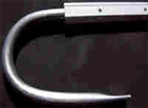
Original product made of copper wire. In the arsenal of experienced craftsmen there is a high-quality and at the same time very simple version of a TV antenna, for the manufacture of which you only need to prepare a piece of wire and a soldering iron. We are talking about a frame hinge product of a narrow range. Such an antenna has a significant advantage - it acts as a powerful selective filter that reduces interference. Thanks to this, the device can receive a high-quality signal.
To avoid common mistakes, you need to correctly determine the length of the loop. This can be done thanks to digital data, which is individual for each region. For example: in St. Petersburg the broadcast occurs at a frequency of 666 and 586 MHz. But, regardless of the region of residence, the calculation formula is always the same: lr = 300/f. The length of the working loop in meters is designated as lr, but the average frequency range is f. You can set the last value for St. Petersburg as follows (666+586)/2=626.
When all the data is available, you can safely determine the optimal length: lr 300/626 = 0.48, which means that the master will need 48 centimeters of wire. To make the finished product better and more durable, you can use a powerful RG-6 cable for its manufacture, where there is a special foil in the braid.
Making such an antenna should correspond to the following diagram:
- Initially, the master must cut a piece of wire or RG-6 cable, the length of which must fully correspond to the received lr data.
- A working loop of suitable diameter is carefully rolled up, and after that a cable is soldered to it, which goes to the receiver. If the master decides to use the more durable RG-6, then before using it you need to remove the insulation from both ends (about 2 centimeters). It is worth noting that the central core does not need to be cleaned, since it is not used in soldering.
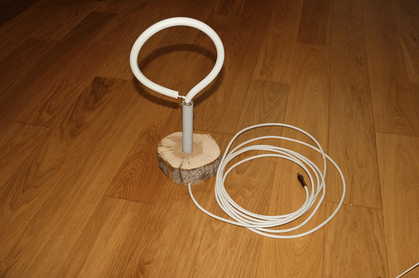
- The finished receiver is installed on a special stand.
- A special plug (F-connector) is screwed onto the cable itself, which leads to the receiver.
An important fact is that, despite the simplicity of the design, this particular type of antenna is one of the most effective for receiving a digital signal. But, provided that all calculations were made as correctly as possible.
Compact model
 Despite the unusual design of this antenna, it is quite functional, since it is presented in the form of the most ordinary dipole. The huge advantage is that the dimensions of a standard beer can are ideal for the shoulders of a UHF active vibrator. When the finished product is installed indoors, the craftsman does not need to coordinate the design with the cable (if its length does not exceed two meters).
Experienced craftsmen note that the arms of such an exotic dipole must always be secured to a holder, which can be made of any insulating material. In this case, home craftsmen often use various improvised things (for example: a mop bar, a plastic clothes hanger, a wooden block). The distance between the shoulders should be from 1 to 9 cm (selected exclusively empirically). The main advantages of the design include the speed of its production - a maximum of 25 minutes, as well as excellent broadcast quality.
Universal diamond-shaped signal receiver
This is one of the simplest, but at the same time durable and reliable antennas, which was in great demand in the era of on-air television broadcasting. The device itself is presented in the form of a simplified model of a classic zigzag.

Experts have found that to increase sensitivity, the unit must be equipped with capacitive inserts, as well as a powerful reflector. If the reception level is at a high level, then there is no need to equip the product with additional elements.
As the main material, you can safely use brass, aluminum or copper tubes/strips 15 millimeters wide. If the master will install the finished structure on the street, then it is better to refuse aluminum products, since they are most susceptible to the negative effects of corrosion. Special capacitive inserts are made of durable sheet metal, regular foil or metal mesh. After installation, they must be soldered along the entire circuit. Professional cable laying also has its own nuances: the wire should not have any bends, and it should not leave the side insert.
Making your own high-quality log-periodic UHF antenna is not so difficult, the main thing is follow the basic recommendations of specialists. Moreover, the installation of finished structures can take place both in the house and on the roof. But, it is important to remember that the higher the antenna is located, the better the quality of the received signal will be.
The modern market offers a huge range of antennas for receiving terrestrial television. There are two main types of these products that allow you to receive meter and decimeter radio waves. They can also be divided according to the place of use into outdoor and indoor. Fundamentally, they are not much different. Here, first of all, the emphasis is on size and maintaining the necessary parameters under the influence of weather conditions. In this article we will discuss existing types of these products, consider what parameters they have, and how to conduct testing. And for those who like to tinker, we’ll tell you how to make a decimeter antenna with your own hands.
What's the difference?
Let's try to explain in a nutshell how to determine what type of product is in front of you. The UHF antenna looks like a ladder. Install them parallel to the ground. Meter ones are crossed aluminum tubes. The appearance of both types is shown in the photo below. There are also combined antennas, when both the “ladder” and cross tubes are combined.
Problem of choice
It would seem that everything is simple. However, the buyer is faced with the question of how to choose the right device and what parameters to pay attention to. In general, it is best to test TV antennas directly in the conditions in which they will operate. The passage of a radio signal is often individual for a particular area. Thus, a product shows the same results in laboratory conditions, but completely different results in the field. There are certain tactics that allow you to test both meter and decimeter TV antennas. However, when choosing such a product in a store, we do not have the opportunity to conduct full testing. Not a single seller will agree to give us several different antennas to test. In this case, you have to trust the characteristics of these products. And hope that the selected antenna will perform its functions according to the passport data, and not real conditions.

Main settings
A decimeter antenna is characterized primarily by its radiation pattern. The main parameters of this characteristic are the level of the side (auxiliary) lobes and the width of the main lobe. The width of the diagram is determined in the horizontal and vertical planes at a level of 0.707 from the largest value. So, according to this parameter (the width of the main lobe), diagrams are usually divided into non-directional and directional. What does this mean? If the main lobe has a narrow shape, then the antenna (decimeter) is directional. The next important parameter is noise immunity. This characteristic primarily depends on the level of the back and side lobes of the diagram. It is determined by the ratio of the power released by the antenna, subject to a consistent load at the time of receiving a signal from the main direction, to the power (with the same load) when receiving from the side and rear directions. First of all, the shape of the diagram depends on the number of directors and the design of the antenna.
What does the term “wave channel” mean?
TV antennas of this type are very effective directional receivers of radio signals. They are widely used in areas of clearly weak television airwaves. The antenna (decimeter) of the “wave channel” type has high gain and good directivity. In addition, these products have relatively small dimensions, which (along with the high level of amplification) makes it very popular among residents of holiday villages and other settlements remote from the center. This antenna also has a second name - Uda-Yagi (named after the Japanese inventors who patented this device).

Principle of operation
A decimeter antenna of the “wave channel” type is a set of elements: passive (reflector) and active (vibrator), as well as several directors, which are installed on a common boom. The principle of its operation is as follows. The vibrator has a certain length, it is located in the electromagnetic field of the radio signal and resonates at the frequency of the received signal. In it, an electromagnetic field is induced on each passive element, which also leads to the occurrence of EMF. As a result, they re-emit secondary electromagnetic fields. In turn, these fields induce additional EMF on the vibrator. Therefore, the dimensions of the passive elements, as well as their distances to the active vibrator, are chosen such that the EMF induced by them due to secondary fields is in phase with the main EMF, which is induced in it by the primary electromagnetic field. In this case, all EMFs are summed up, which increases the efficiency of the design compared to a single vibrator. Thus, even an ordinary room can provide stable signal reception.
The reflector (passive element) is installed behind the vibrator 0.15-0.2 λ 0. Its length should exceed the length of the active element by 5-15 percent. Such an antenna produces a one-way directional pattern in the vertical and horizontal planes. As a result, the reception of reflected signals and fields that come from the back of the antenna is significantly reduced. If it is necessary to receive a television signal over long distances, as well as in difficult conditions, in the presence of a lot of interference, it is recommended to use a three or more element antenna, which consists of an active vibrator, one or more directors and a reflector.

Direct and reflected signals
In an article devoted to a wave receiving device (“Tele-Sputnik” No. 11 for 1998), it was noted that in the case when the signal source is not a standard (that is, not a laboratory) generator and emitting antenna, and the signal is broadcast by a television tower, a significant Weather conditions play a role, as does the location where the receiver is installed. This especially affects the operation of UHF products. This is explained by the fact that in the decimeter range there is less, and accordingly, obstacle avoidance is much worse, and any signal reflections play an important role in the quality of the received picture. In particular, even the wall of a house can be a wave reflector. So, in conditions where there is no direct visibility, this property can be used - to receive the reflected signal. However, its quality will be lower than that of the direct one. If the level of the transmitted signal is high, but there is no line of sight, then you can use the reflected wave. In fact, an indoor decimeter antenna works precisely on this principle. After all, it is difficult to catch a direct wave in a room if the windows face the opposite direction. Therefore, if you try, you can always find a point where the received signal will be higher. But in the case of direct visibility, any reflected interference will spoil the received picture.
A technique that allows you to compare antenna parameters
In order to test receiving devices, they need to create the same conditions:
1. Select the installation location where your antenna will operate. You can use a balcony, roof or mast. The main thing is that both the height and the location are the same for all products.
2. The direction to the source of the broadcast signal should be maintained with an accuracy of three degrees. To do this, you can make a special mark on the mounting pipe.
3. Measurements should be carried out under the same weather conditions.
4. The cable connecting the antenna and the TV must have the same resistance and length. It is best to use one wire, changing only the receivers.
Testing should only be carried out on products of one type. For example, an indoor UHF antenna should not be compared with an outdoor one or with meter receivers. It should be understood that field tests may produce results that differ significantly from laboratory tests.

UHF antenna for digital television
Recently, the media have been increasingly talking about the need to switch to digital television. Many have already done this, and some are still thinking about it. So far, the signal is broadcast in both modes. However, the quality leaves much to be desired. In this regard, people are interested in what decimeter antennas can be used for T2. Let's look at this issue. Essentially, digital television broadcasts on a UHF channel. So a standard UHF antenna may be suitable for receiving it. You can often see receivers in stores that indicate that they are intended for digital television. However, this is a marketing ploy that allows you to sell a standard decimeter antenna for more than it costs. When purchasing such a product, you will not have a guarantee that it will provide better reception than what you already have in your home and has been working for more than one year. As we said earlier, the quality depends mainly on the level of the broadcast signal and line of sight conditions. However, it should be borne in mind that in most cities, significantly more powerful generators are used for transmitting digital television than for analogue. This is done in order to speed up the transition to the new standard. After all, viewers want to see a clear image, and not “snow” on the screens. Therefore, if there is a receiver in the window that says “UHF antenna for DVB T2”, know: this does not mean that this is some kind of special product. It’s just that a not entirely honest seller wants to profit from an uninformed buyer. You should also know that the transition program to the new standard provides for the creation of advisory centers. In them you can get comprehensive information on any issue related to digital television. All consultations are provided free of charge. In some cities, this equipment is in test mode, so the signal may be unstable or weakened. Don’t worry, the center staff will always tell you how to solve the problem with signal reception quality.

DIY decimeter antenna
The length of UHF waves falls within the range from 10 cm to 1 m. Their name comes from this feature. At this frequency they propagate predominantly in a straight line. They practically do not bend around obstacles and are only partially reflected by the troposphere. In this regard, long-distance communication in the UHF range is very difficult. Its radius does not exceed one hundred kilometers. Let's look at a couple of examples of how to make a decimeter antenna at home.
The first version of a homemade television broadcast receiver will, so to speak, be assembled on the knee from scrap materials. UHF channels are located in the range from 300 MHz to 3 GHz. Our task is to produce an antenna that will operate precisely at these frequencies. For this we need two 0.5 liter beer cans. If you use a larger capacity, the received frequency will decrease. For installation you will need some kind of frame; you can use a board 10 cm wide. You can also use a regular wooden hanger, in which case the resulting antenna can be hung on a nail in any convenient place in the room. In addition to the frame and cans, you need to prepare a pair of self-tapping screws, tools, a coaxial cable, a connector, terminals, and insulating tape. We put a television connector on one end of the cable and solder it. We insert the second end into the terminal block. Next, we attach the terminals to the necks of the cans with screws. The wires should fit snugly to the metal. Now let's start assembling the antenna itself. To do this, we secure the jars on a horizontal crossbar with their necks facing towards each other. The distance between them should be 75 mm. You can use insulating tape to secure the cans. That's it, the antenna is ready! Now we need to find a place for stable reception of a television signal and hang our “hanger” in this place.

Receiver for digital television
This section is intended for people who do not want to use a regular (analog) product, but want a special UHF antenna to be used for the new format. It is also easy to assemble such a receiving device with your own hands. To do this, we will need a square wooden (or plexiglass) frame with a diagonal of 200 mm and a regular RK-75 cable. The option presented to your attention is a zigzag antenna. It has proven itself to be excellent when working in the digital television reception range. Moreover, it can be used in places where there is no direct visibility to the signal source. If your broadcast is weak, you can connect an amplifier to it. So let's get to work. We strip the end of the cable by 20 mm. Next, we bend the wire into a square shape with a diagonal of 175 mm. We bend the end outward at an angle of 45 degrees, and bend the second stripped end to it. We connect the screens tightly. The stripped central core hangs freely in the air. On the opposite corner of the square, carefully remove the insulation and screen over a 200 mm area. This will be the top of our antenna. Now we connect the resulting square with a wooden frame. At the bottom, where the two ends are connected, copper staples made from thick wire should be used. This will ensure better electrical contact. That's all, the decimeter antenna for digital television is ready. If it will be installed outside, you can make a plastic case for it, which will protect the device from precipitation.