
Wiring diagram in the apartment: electrical wiring for different rooms. Do-it-yourself wiring: from a diagram to installation What is the principle of forming consumer groups
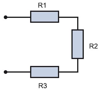
Parallel- with this method, the elements included in the chain are united by two nodes and are not connected to each other. With such a connection of the elements, even if one of the lamps burns out and breaks the circuit, the rest will not go out, since the current will have “bypass” paths.
Sequential- all elements of the chain are located one after another and do not have nodes. An example of a serial connection is the well-known Christmas tree garland: a large number of light bulbs connected by one wire. If one burns out, the chain will break and all will go out.
There are three main types of electrical wiring. Let's consider them in detail, since the whole scheme depends on the type chosen.
1. star type sometimes called boxless, or European, type of wiring. In short, this type can be displayed as follows: one outlet - one cable line to the shield. This means that each socket and lighting point has a separate cable line that goes directly into the apartment panel and ideally has a circuit breaker. What are the advantages and disadvantages of this type of wiring? Plus - first of all, in safety and the ability to control each electrical point. In addition, there is no need to install junction boxes. This type of wiring is done when a smart home system is installed. Minus the "stars" - at least three times the consumption of wiring and, accordingly, labor costs for its installation. In addition, the housing shield becomes the size of an average closet. It can include 70–100 groups of automata, especially if the facility also has information networks. It is difficult to install such a shield on your own, and it is more expensive than usual.
2. Loop type resembles a "star", but differs from it in efficiency. You can depict it like this: a socket - a socket - a socket - an apartment shield or a junction box. Several electrical points are connected in series to one cable, from which a common supply conductor goes either to the apartment shield or to the junction box.
3. Type of wiring in junction boxes- the most common variant. This is how wiring was done in Soviet times. An economical way that does not require special expenses. There is no shield in the apartment at all, it is located on the landing. An apartment branch departs from such a common supply "riser". There is a meter and a circuit breaker on it in the shield (sometimes - 1, sometimes - 2-3, rarely more). The supply cable enters the apartment, then with the help of junction boxes - into the premises, approaching each point. We can say that from the junction box, the wiring goes to the "star" points.
In its pure form, wiring types are rarely used. Based on available resources and optionally, a mixed type is usually selected. An example of wiring in a separate apartment.

Two types of wiring: socket - shield ("star") and shield - socket - socket - socket ("loop")
The power cable is included in the apartment shield, where there are several groups of automatic machines and protection devices. In the shield, the common cable is routed into several zones, for example, in living rooms and separately in the bathroom and kitchen, divided into sockets and lighting. The power cable of a separate zone enters the room and is distributed in a box by points. Options are possible here: the cable will go to the sockets with a “loop” or a separate wire will be allocated to each point.

Serial "loop" and parallel in junction boxes
Professional electricians draw up such circuits taking into account all factors. These are the wishes of the owner of the object, that is, what exactly you want to see in an apartment or house. For example, the owner says that the living room should have two groups of outlets, three in each. Plus two walk-through switches and telephone sockets in the amount of three pieces. The electrician, having taken into account these data, according to the rules of electrical work, draws up a diagram that takes into account safety parameters, the procedure for performing work, the type of wiring, the dimensions of the strobe, etc. Such a drawing is a document and is certified by a special organization.
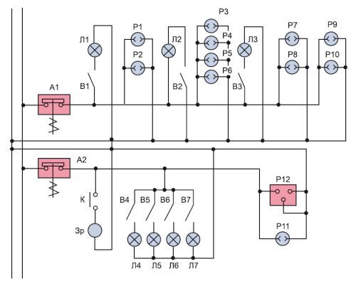
An example of a schematic diagram of the power supply of an apartment, compiled by a professional electrician
Modern firms providing services for electrical work use computer programs. They were created specifically for engineering and technical workers (ITR) and are unlikely to be useful to a home master.
To do the wiring yourself, you can draw the diagram yourself. This is done quite simply. To begin with, an apartment plan is depicted, taking into account all sizes. If the necessary documentation is not available, you can take it from the developer, although it must also be kept by the owner of the home.
Then, using special symbols, all the desired points are set: lamps, sockets, circuit breakers, etc. You must not be too lazy and put generally accepted symbols so that other people understand this scheme. There are frequent cases when, after some time, the author of the scheme cannot figure out the mysterious hieroglyphs, which he himself invented. After that, lines are drawn that indicate the wiring. Be sure to indicate on the plan how far from the ceiling or floor the cable is, especially if the wiring is hidden.

The following is an example of an electrical circuit of an apartment. Different colors show lighting wires, power cables and ground wire. Conventional icons depict lamps, sockets, switches and junction boxes. Such a scheme is very clear, and all the necessary calculations can be performed on it. This is necessary in order to know exactly where the wires go in the future. Otherwise, when hanging a picture or a shelf, you can get a drill directly into the cable.

There are standard rules for installation. They are:
1. The wire is laid only along vertical and horizontal lines at right angles. If there is a desire to cheat and save the cable by running it diagonally, it is better not to do this. In the future, it is very difficult to find this curved path, and getting into it with a nail is as easy as shelling pears.
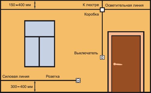
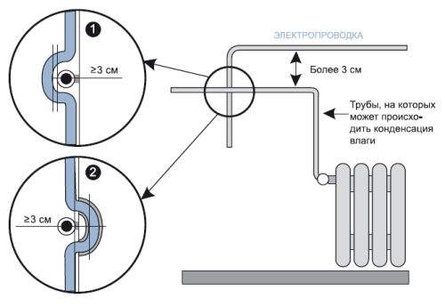
2. The distance from the wire to the ceiling or floor should be 15 cm. From the corners, door jambs and window frames - at least 10 cm. When tracing through heating pipes, a gap between them and the wiring should be at least 3 cm.
3. Avoid crossing wires when laying. If this is difficult, then the distance between the cables should be at least 3 mm.
4. To simplify calculations, all sockets and switches should be at the same height. Usually, switches are installed to the left of the door at a height sufficient to touch them with a lowered palm, that is, 80–90 cm. Sockets are mounted at a height of 25–30 cm. However, in the kitchen and in the case of connecting high-hanging electrical appliances, this distance may be and others. It is best if the wire to the switches will go down from above, and to the sockets from below - this is what most electricians do.
5. The length of the conductor coming out of the electrical point should be 15–20 cm. This is done for the convenience of mounting points with a hidden type of wiring. If it is of an open type, then the length of the conductor may be less: 10–15 cm.
The ends of the cores of wires that go into electrical points must be insulated with electrical tape. Armed with a drawing, you can begin to mount the wiring.
When changing the electrician in the apartment, you need to know exactly where and which electrical points will be installed, so you need to start this process with the development of a wiring diagram, and it cannot be otherwise. It is impossible to start installation without a diagram, one without the other is impossible, any professional electrician knows this.
When developing a wiring diagram, many questions arise, such as the choice of the cross-section of conductors, the installation location of sockets and switches, the planned load, depending on the power of electrical appliances, as well as the protection of the circuit itself, electrical appliances and a person from emergency operation. Therefore, when repairing electrical wiring, or completely replacing it, these issues should be given maximum attention.
If, for some reason, the existing wiring diagram of the apartment does not suit the owner, for example, because the current loads do not match the cross section of the conductors, the location of sockets and switches, or for some other reason, you should think about repairing the wiring and turn to electricians for help . Unless of course you yourself are not an expert in this field.
In many apartments, a circuit with aluminum wiring is still in operation, at the time when it was designed and these buildings were being built, there were no such large electrical loads, and the requirements for the wiring diagram of apartments were different.
The absence of a grounding conductor, the use of aluminum wires for wiring, the lack of high-quality protection (RCD, modern machines) are the main, but far from the only, disadvantages of outdated circuits. The operation of such electrical wiring can be dangerous to human life.
So, as many people install in their apartments instead of jacuzzi bathtubs to which a voltage of 220 V is supplied, the wiring diagram of the apartment must be three-wire, have three wires, phase, zero, earth, and the line must also be protected by an RCD, the same requirement applies to on other electrical appliances such as washing machine, electric oven, dishwasher, etc. Sometimes there are fires due to a short circuit in the old electrical wiring.
If all this is not indifferent to you, you should determine how old your wiring is, what work needs to be done to correct the current situation, repair the wiring or only partially replace it, what materials to buy? But it is better to entrust all this to our professionals! What will be the wiring diagram of the apartment? It all depends on how many rooms in the apartment, on the power consumption, on the number of electrical appliances.
Typical wiring diagrams in the apartment.
When developing a circuit, an electrician must necessarily take into account such nuances as the location of sockets and switches in rooms so that they are not subsequently covered by furniture. If you contact us, we will take into account all the points, grounding of electrical appliances, power and selection of the conductor section, installation of modern protection (RCD, automatic devices).
So, if the apartment has a standard layout, you can use the ready-made scheme developed for typical apartments by making minor adjustments. It is shown in the figure below.
Figure 1 is a schematic diagram of the electrical wiring of the apartment.

Figure 2 is a single-line wiring diagram of an apartment.
A mandatory requirement is the installation of a potential equalization system. To do this, it is necessary to connect the ground bus in the electrical panel with pipes of cold, hot water and sewage, as well as with a bathroom, as shown in the diagram, Figure 2, with a separate wire. 1.7.82, 1.7.83, 7.1.87, 7.1.88 PUE 7th edition.
This diagram shows the connection of the wiring of the apartment to the three-phase power supply of the riser of the house. A VVG 5 * 16 brand cable enters the apartment shield from the floor shield, that is, the input to the apartment. The input is a five-wire cable from which the entire apartment is powered. N is the working zero. L1,L2,L3 are phase numbers. PE is protective earth.
The switchboard in the apartment is arranged as follows: the input cable is connected to the introductory machine, from the introductory machine there are jumpers with a cable or bus to group machines, a lighting network, a socket network and other electrical appliances.
We draw up a wiring diagram for the apartment.
First, you need to find out what electrical appliances will be used in the apartment and where they will be installed. Let's start with the kitchen, as the most powerful appliances are traditionally concentrated in this place. One of them is an electric stove, on which a separate cable is laid from the electrical panel of the VVG 3x6 brand and a separate machine is installed. A separate cable is also laid directly from the shield to other powerful electrical equipment, such as a washing machine and dishwasher, water heater, underfloor heating, and air conditioning.
For the rest of the sockets in the apartment, you can pass a common cable to the junction box, and from it you can already wire the cable to each socket or block of sockets. We will do the same with lighting, we will throw a common wire on the box, and from the box we will make the wiring to the lamps and switches.
Thus, we get a scheme in which the power supply of the entire load of the apartment is divided into group lines. Such as lighting group, household socket group, power socket group.

Figure 3. Simplified block diagram of the electrical wiring of the apartment.
Having drawn up a schematic diagram and knowing the area, cable laying locations, installation locations for sockets and switches, you can begin to calculate the amount of materials that will be required for installation. The wiring diagram of the apartment will help us calculate the cable footage, the number of sockets and switches, purchase the right number and type of machines, and choose an electrical panel.
Here are a couple more circuits that will be more understandable for non-professional electricians or people with a superficial understanding of electricity. The diagram clearly shows cables, circuit breakers, as well as consumers of electricity.

Figure 4. Schematic diagram of the wiring of a one-room apartment.

Figure 5. Structural diagram of the electrical wiring of the apartment.
- Shield plastic case
2. Clamping elements of zero working conductors
3. Clamping element of zero protective conductors, as well as a potential equalization conductor
4. Clamping element of input terminals of protective devices of group circuits
5. Residual current switch (RCD)
6. Machine guns
7. Group lines
How to determine the scheme of an existing electrical wiring.
It is not difficult to determine how the wiring in the apartment is done if you know some of the rules by which it is laid. Installation schemes may be different depending on the type of house and on the year of its construction, but it is still possible to determine the wiring layout for the apartment.
in brick houses wiring can be done in two ways. The first way is the upper wiring not lower than 15 cm from the ceiling level. At the same level, junction boxes are placed, from which descents are made to sockets and switches. All wires are laid strictly vertically and horizontally in the shtrabe. Cables for lighting are laid in ceilings, in which there are voids (channels).
The second way is the lower wiring, when the cables are laid in pipes along the floor and filled with a screed, the cables rise vertically from the floor to the junction boxes and the wiring is already being done from them. Lighting is also carried out in the channels of ceiling ceilings.
In panel houses, Khrushchev electrical wiring is carried out in the channels of the plates. Channels for wiring, places for installing sockets, switches, are made at the factory during the manufacture of plates. All channels converge into junction boxes, from which channels go to the electrical panel. In panel houses, channels are often made not vertically and horizontally, but along the shortest path, that is, along an oblique line.
In some Khrushchev houses, the wiring for powering sockets is thrown under your floor, and the wiring for lighting under the floor of your neighbors is from above.
At the end of the topic, some useful tips. If you are doing electrical repairs.
The installation height of sockets and switches from the floor level can be any, the main thing here is that it is convenient for you to use them. In general, there is one according to which sockets should be at a height of 30 centimeters from the floor, and switches - 90 centimeters. In general cases, this placement is usually the most convenient. But sockets in the kitchen would obviously be more appropriate to place above the desktop surface. The same situation is with the desk.
It is better to connect stationary household appliances, such as an extractor hood, a heated towel rail, a water heater, through a terminal block. Because it is unlikely that you will often use the outlet, and there is not much point in it.
Sockets for the Internet and a TV can be combined into one unit. Thanks to this, you can simultaneously install a low-voltage network and electrical wiring. Decide on the installation site of the low-current shield, whether you install it in the apartment or lead the wires to the floor shield. Choose the most convenient and profitable option.
Wire connections, twists, terminal blocks should be located only in junction boxes, otherwise, after the operation of the wiring, you will not be able to withdraw the wire to connect any devices, if necessary. As a rule, one box is installed in each room, but if there are many electrical outlets in the room, the wires may not fit in one box, so in this situation it is better to install two boxes.
Even 15 - 20 years ago, the load on the power grid was relatively small, but today the presence of a large number of household appliances has provoked an increase in loads at times. Old wires are far from always able to withstand heavy loads and over time there is a need to replace them. Laying electrical wiring in a house or apartment is a matter that requires certain knowledge and skills from the master. First of all, this concerns knowledge of the rules for wiring electrical wiring, the ability to read and create wiring diagrams, as well as skills in electrical installation. Of course, you can do the wiring with your own hands, but for this you must adhere to the rules and recommendations below.
Wiring Rules
All construction activities and building materials are strictly regulated by a set of rules and requirements - SNiP and GOST. As for the installation of electrical wiring and everything related to electricity, you should pay attention to the Rules for the Arrangement of Electrical Installations (abbreviated PUE). This document prescribes what and how to do when working with electrical equipment. And if we want to lay electrical wiring, then we will need to study it, especially the part that relates to the installation and selection of electrical equipment. The following are the basic rules that should be followed when installing electrical wiring in a house or apartment:
- key electrical components such as distribution boxes, meters, sockets and switches should be easily accessible;
- installation of switches is carried out at a height of 60 - 150 cm from the floor. The switches themselves are located in places where the open door does not prevent access to them. This means that if the door opens to the right, the switch is on the left side and vice versa. The wire to the switches is laid from top to bottom;
- sockets are recommended to be installed at a height of 50 - 80 cm from the floor. This approach is dictated by flood safety. Also, sockets are installed at a distance of more than 50 cm from gas and electric stoves, as well as heating radiators, pipes and other grounded objects. The wire to the sockets is laid from the bottom up;
- the number of sockets in the room must correspond to 1 pc. for 6 m2. The kitchen is an exception. It is equipped with as many sockets as necessary to connect household appliances. Installation of sockets in the toilet is prohibited. For sockets in the bathroom outside, a separate transformer is equipped;
- wiring inside or outside the walls is carried out only vertically or horizontally, and the installation location is displayed on the wiring plan;
- wires are laid at a certain distance from pipes, ceilings and other things. For horizontal, a distance of 5 - 10 cm from the floor beams and cornices and 15 cm from the ceiling is required. From the floor, the height is 15 - 20 cm. Vertical wires are placed at a distance of more than 10 cm from the edge of the door or window opening. The distance from the gas pipes must be at least 40 cm;
- when laying external or hidden wiring, it is necessary to ensure that it does not come into contact with the metal parts of building structures;
- when laying several parallel wires, the distance between them must be at least 3 mm or each wire must be hidden in a protective box or corrugation;
- wiring and connection of wires is carried out inside special junction boxes. Connection points are carefully isolated. The connection of copper and aluminum wire to each other is strictly prohibited;
- grounding and neutral wires are bolted to the devices.
Project and wiring diagram
Work on laying electrical wiring begins with the creation of a project and a wiring diagram. This document is the basis for future house wiring. Creating a project and a scheme is quite a serious matter and it is better to entrust it to experienced professionals. The reason is simple - the safety of those living in a house or apartment depends on it. Project creation services will cost a certain amount, but it's worth it.

Those who are used to doing everything with their own hands will have to, adhering to the rules described above, as well as having studied the basics of electrics, independently make a drawing and calculations for the loads on the network. There are no particular difficulties in this, especially if there is at least some understanding of what electric current is, and what are the consequences of careless handling of it. The first thing you need is the symbols. They are shown in the photo below:

Using them, we make a drawing of the apartment and outline lighting points, installation locations for switches and sockets. How many and where they are installed is described above in the rules. The main task of such a scheme is to indicate the installation location of devices and wires. When creating a wiring diagram, it is important to think in advance where, how much and what household appliances will be.
The next step in creating the circuit will be the wiring to the connection points on the circuit. At this point it is necessary to dwell in more detail. The reason is the type of wiring and connection. There are several such types - parallel, serial and mixed. The latter is the most attractive due to the economical use of materials and maximum efficiency. To facilitate the laying of wires, all connection points are divided into several groups:
- lighting of the kitchen, corridor and living rooms;
- toilet and bathroom lighting;
- power supply of sockets in living rooms and corridors;
- power supply for kitchen sockets;
- power supply socket for electric stove.
The above example is just one of many lighting group options. The main thing to understand is that if you group the connection points, the amount of materials used is reduced and the circuit itself is simplified.

Important! To simplify the wiring to the sockets, the wires can be laid under the floor. Wires for overhead lighting are laid inside the floor slabs. These two methods are good to use if you do not want to ditch the walls. In the diagram, such wiring is marked with a dotted line.
Also in the wiring project, the calculation of the estimated current strength in the network and the materials used are indicated. The calculation is performed according to the formula:
I=P/U;
where P is the total power of all devices used (Watts), U is the mains voltage (Volts).
For example, a 2 kW kettle, 10 60 W bulbs, a 1 kW microwave, a 400 W refrigerator. Current strength 220 volts. As a result (2000+(10x60)+1000+400)/220=16.5 Amps.
In practice, the current strength in the network for modern apartments rarely exceeds 25 A. Based on this, all materials are selected. First of all, this concerns the cross section of the wiring. To facilitate the selection, the table below shows the main parameters of the wire and cable:

The table shows the most accurate values, and since the current can fluctuate quite often, a small margin is required for the wire or cable itself. Therefore, all wiring in an apartment or house is recommended to be made of the following materials:

- wire VVG-5 * 6 (five cores and a cross section of 6 mm2) is used in houses with a three-phase power supply to connect the lighting shield to the main shield;
- wire VVG-2 * 6 (two cores and a cross section of 6 mm2) is used in houses with a two-phase power supply to connect the lighting shield to the main shield;
- wire VVG-3 * 2.5 (three cores and a cross section of 2.5 mm2) is used for most of the wiring from the lighting panel to junction boxes and from them to sockets;
- wire VVG-3 * 1.5 (three cores and a cross section of 1.5 mm2) is used for wiring from junction boxes to lighting points and switches;
- wire VVG-3 * 4 (three cores and a cross section of 4 mm2) is used for electric stoves.

To find out the exact length of the wire, you will have to run a little around the house with a tape measure, and add another 3-4 meters of stock to the result. All wires are connected to the lighting panel, which is installed at the entrance. Protection circuit breakers are mounted in the shield. Usually this is an RCD for 16 A and 20 A. The former are used for lighting and switches, the latter for sockets. For an electric stove, a separate RCD is installed at 32 A, but if the power of the stove exceeds 7 kW, then an RCD is installed at 63 A.

Now you need to calculate how many sockets and distribution boxes you need. Everything is pretty simple here. Just look at the diagram and make a simple calculation. In addition to the materials described above, various consumables will be required, such as electrical tape and PPE caps for connecting wires, as well as pipes, cable channels or boxes for electrical wiring, socket boxes.
Installation of electrical wiring
There is nothing super complicated in the work on the installation of electrical wiring. The main thing during installation is to follow the safety rules and follow the instructions. All work can be done alone. From the installation tool, you will need a tester, a puncher or a grinder, a drill or a screwdriver, wire cutters, pliers and a Phillips and slotted screwdriver. A laser level would be helpful. Since without it it is quite difficult to make vertical and horizontal markings.
Important! When carrying out repairs with the replacement of wiring in an old house or apartment with hidden wiring, you must first find and, if necessary, remove the old wires. For these purposes, a wiring sensor is used.
Marking and preparation of channels for electrical wiring

We start installation with markup. To do this, using a marker or pencil, we put a mark on the wall where the wire will be laid. At the same time, we observe the rules for placing wires. The next step is to mark the places for the installation of lighting fixtures, sockets and switches and a lighting panel.
Important! In new houses, a special niche is provided for the lighting shield. In the old ones, such a shield is simply hung on the wall.

Having finished with the markup, we proceed either to the installation of wiring in an open way, or to the chasing of walls for hidden wiring. First, with the help of a perforator and a special nozzle of the crown, holes are cut out for the installation of sockets, switches and junction boxes. For the wires themselves, strobes are made using a grinder or a puncher. In any case, there will be a lot of dust and dirt. The depth of the groove of the strobe should be about 20 mm, and the width should be such that all wires fit freely into the strobe.

As for the ceiling, there are several options for resolving the issue with the placement and fixing of the wiring. The first - if the ceiling is suspended or suspended, then all the wiring is simply fixed to the ceiling. The second - a shallow strobe is made for wiring. The third - the wiring is hidden in the ceiling. The first two options are extremely simple to implement. But for the third, some explanations will have to be made. In panel houses, ceilings with internal voids are used, it is enough to make two holes and stretch the wires inside the ceiling.
Having finished with the gating, we proceed to the last stage of preparation for wiring. Wires to bring them into the room must be pulled through the walls. Therefore, you will have to punch holes with a puncher. Usually such holes are made in the corner of the premises. We also make a hole for the wire plant from the switchboard to the lighting panel. Having finished the wall chasing, we begin the installation.
Installation of open wiring

We begin installation with the installation of a lighting shield. If a special niche was created for it, then we place it there, if not, then we simply hang it on the wall. We install an RCD inside the shield. Their number depends on the number of lighting groups. The shield assembled and ready for connection looks like this: in the upper part there are zero terminals, grounding terminals at the bottom, automatic machines are installed between the terminals.

Now we start the wire VVG-5 * 6 or VVG-2 * 6 inside. From the side of the switchboard, the electric wiring is connected by an electrician, so for now we will leave it without connection. Inside the lighting panel, the input wire is connected as follows: we connect the blue wire to zero, the white wire to the top contact of the RCD, and connect the yellow wire with a green stripe to ground. RCD automata are interconnected in series at the top using a jumper from a white wire. Now let's move on to the wiring in an open way.

On the lines outlined earlier, we fix boxes or cable channels for electrical wiring. Often, with open wiring, they try to place the cable channels themselves near the plinth, or vice versa, almost under the very ceiling. We fix the wiring box with self-tapping screws in increments of 50 cm. We make the first and last hole in the box at a distance of 5 - 10 cm from the edge. To do this, we drill holes in the wall with a puncher, hammer the dowel inside and fix the cable channel with self-tapping screws.
Another distinctive feature of open wiring are sockets, switches and distribution boxes. All of them are hung on the wall, instead of being walled in. Therefore, the next step is to install them in place. It is enough to attach them to the wall, mark the places for fasteners, drill holes and fix them in place.

Next, we proceed to the wiring. We start by laying the main line and from the sockets to the lighting panel. As already noted, we use the VVG-3 * 2.5 wire for this. For convenience, we start from the connection point towards the shield. We hang a label on the end of the wire indicating what kind of wire and where it comes from. Next, we lay the wires VVG-3 * 1.5 from switches and lighting fixtures to junction boxes.

Inside the junction boxes, we connect the wires using PPE or carefully insulate them. Inside the lighting panel, the main wire VVG-3 * 2.5 is connected as follows: brown or red wire - phase, connected to the bottom of the RCD, blue - zero, connected to the zero bus at the top, yellow with a green stripe - ground to the bus at the bottom. With the help of a tester, we “ring” all the wires in order to eliminate possible errors. If everything is in order, we call an electrician and connect to the switchboard.
Installation of hidden electrical wiring
Hidden wiring is quite simple. A significant difference from the open one is only in the way the wires are hidden from the eyes. The rest of the steps are almost the same. First, we install a lighting shield and RCDs, after which we start and connect the input cable from the side of the switchboard. We also leave it unconnected. This will be done by an electrician. Next, we install distribution boxes and socket boxes inside the niches made.

Now let's move on to the wiring. We are the first to lay the main line from the VVG-3 * 2.5 wire. If it was planned, then we lay the wires to the sockets in the floor. To do this, we put the VVG-3 * 2.5 wire into a pipe for electrical wiring or a special corrugation and lay it to the point where the wire is output to the sockets. There we place the wire inside the strobe and put it into the socket. The next step will be laying the VVG-3 * 1.5 wire from switches and lighting points to junction boxes, where they are connected to the main wire. We isolate all connections with PPE or electrical tape.

At the end, we “ring” the entire network with the help of a tester for possible errors and connect it to the lighting panel. The connection method is similar to that described for open wiring. Upon completion, we close the strobes with gypsum putty and invite an electrician to connect it to the switchboard.
Laying electricians in a house or apartment for an experienced craftsman is quite an easy task. But for those who are not well versed in electrics, you should take the help of experienced professionals from start to finish. This, of course, will cost money, but this way you can protect yourself from mistakes that can lead to a fire.
In the practice of any home master, questions periodically arise related to the finalization of the electrical circuit, when it is necessary to install an additional outlet, hang a new lamp, or completely re-equip the room.
The question immediately arises: how is the electrical wiring diagram made, where should I connect to it?
The situation is aggravated when the building is old, the apartment has changed several owners, each of whom carried out repairs to his taste. As a result, all electrical connection points are hidden inside the decorative coatings, and the routes for laying cables and wires are unknown.
The principles of building an electrical circuit in an apartment
Any wiring is created according to general methods and is somehow different from all other laying schemes.
Required schema elements
The basis for creating electrical wiring is, to which electricity is supplied from the supply organization. It can be installed at the entrance to a private house, on the landing of the entrance of a multi-storey building - storey or directly inside the apartment.
Electricity in the apartment shield from the input immediately goes to the electric meter - a device that takes into account its consumption. After it, it is distributed along the supply lines to consumers by cables and wires.
To protect the circuits, automatic devices are used that cut into the circuit inside the apartment shield in front of the cable going to the consumer.
Distinctive features
Each specific wiring diagram necessarily differs from similar developments due to the use of numerous designs of various models of electrical devices, wires and cables with their installation according to standard or individual projects by different methods.
Ways to supply voltage to consumers in the apartment
The electric current from each operating household appliance is summed up in the apartment shield and taken into account by the meter through which the total load passes. Therefore, the current-carrying lines of the apartment shield are made with a thick section, which excludes thermal overload of the wiring, aging of the insulation.
To consumers from the apartment shield, wires are laid with a smaller cross section: the load through them is lower. But the material and cross-section of the core are selected according to reference books that take into account the operating conditions of the wires and the power transmitted through them.
In this case, there are three ways to implement the scheme:
a loop (tires), when a common wiring trunk is created through junction boxes, and from them there are branches to electrical points (sockets, switches, lamps);
the radial method, which consists in supplying voltage to each outlet with a separate cable that goes directly without breaks and connections from the protection of the apartment shield;
in a combined way, combining elements of the first two principles.
Loop voltage supply
All ends of electrical wires and cables are switched inside junction boxes. To connect them, a disconnect map is created.
An example is the wiring diagram used in multi-storey residential buildings forty years old. As an example, consider the structure of the old wiring of a one-room apartment.

An electric meter and two automatic switches were mounted inside the access shield. One was used for the socket group, and the second worked for lighting. Cables or more often wires went from them in a loop - “aluminum noodles” to three (sometimes four) junction boxes:
1. rooms;
3. san node and bathroom.
Both loops were laid in parallel lines to each box, switched in it. Since earlier the loads on the electrical wiring were small, the separation by wire thickness was not used. The whole circuit was completely mounted with a cross section of aluminum conductors of 2.5 mm2.
The junction box for the sanitary unit and the bathroom was installed in the corridor and connected by wires to the one that controls the lighting of both rooms.
The diagram shows a variant of consumer protection, connected separately to sockets and lighting devices. The principle of managing consumers by their location in the rooms was also often used. For example, AB No. 1 protects the equipment of the kitchen and bathroom, and No. 2 - the corridor and the room.
Inside one room, several sockets were often connected with a cable, and lighting was done with a three-arm chandelier controlled by a two-gang switch.
The supply of voltage to consumers can also be carried out according to other principles, when part of the load is connected through the third backup circuit breaker of the apartment shield. To determine the method of connecting sockets and switches, proceed as follows:
light all lamps and plug in working electrical appliances, for example, a table lamp or a razor;
turn off any circuit breaker in the shield and monitor the consumers that have stopped working;
record for memory;
turn off the next machine and fix the changes;
analyze information.
Voltage supply by radial method
The housing shield distributes electricity to circuit breakers, as in the previous case. In this situation, they are more carefully selected according to the technical characteristics for each consumer according to the individual load current.

The cable connects sockets, switches and lamps directly to circuit breakers without using any additional connections.
With this principle, the electrical wiring provides increased reliability of operation by disconnecting from the protection only the consumer on which the malfunction occurred. However, in this case you need:
increased number of circuit breakers;
large dimensions of the apartment shield for their placement;
long cable lines.
Due to this, the material costs of creating the circuit and its cost increase.
Voltage supply by combined method
The method combines two developments: a loop and a radial connection, taking into account their application to local conditions. Due to the correct selection of loads, reasonable cost savings are created.

Principles of laying cable lines
Whatever scheme of electrical connections is chosen, for its implementation it is necessary to connect the automatic switches of the apartment panel with consumers with wires.
There are the following ways of cabling on building structures:
along the ceiling;
on the walls;
under the floor;
mixed method.
Ceiling cable routing
The traditional old scheme, which is often resorted to now.

Cables from sockets, switches and a shield rise along vertical lines to the ceiling and under it go into the ceiling. When it becomes necessary to turn and connect the wires to the junction box, for example, to connect the switch, then only a right angle is created at least 15 cm from the top.
This method allows you to avoid accidental damage to hidden wiring in the future when drilling walls for mounting shelves, paintings and other elements.
Cable routing on the wall
The method is similar to the previous one, but the cable lines are directed only along the walls.

There may be obstacles on the way of the electric main: pipelines for water supply, sewerage, heating, gas pipelines. They must be bypassed, creating an air gap as an insulating, separating section of at least 3 cm.

Laying cables on the floor
This method has been used relatively recently in the construction of new buildings. The cables from the apartment shield are lowered down, laid under the floor covering, and protected from mechanical stress. They are led vertically to the sockets.

When connecting sockets with a loop, the jumpers are laid along the floor in pipes or the walls are ditched.
To connect fixtures and switches, junction boxes are mounted.
Features of laying electrical wiring in panel houses
With the in-line factory method of manufacturing multi-storey buildings, the same type of templates for wall and ceiling panels are created. Inside them, empty channels for laying wires are immediately made.
For technological reasons, their direction may differ from the strict vertical and horizontal orientation.
The first panel buildings, called Khrushchev, have a specific electrical wiring laid under the wooden floor of the apartment. It rises vertically to the sockets in the cavities of the walls, and to the lamps and switches it is supplied through a hole in the neighbor's concrete floor slab from above.
In this way, they used to try to save material costs for wiring, but they neglected the safety elements.
How to make a do-it-yourself wiring diagram in an apartment
Electrical equipment requires compliance with strict operating rules. Incorrect connection to the mains voltage creates an increased risk of household injuries. For this reason, all electrical work is carried out by trained professionals who have been trained and passed exams.
Independent connection of electrical appliances is usually not very difficult, it ends successfully even if you make a few small mistakes. However, when engaging in such activities, it is necessary to first study the safety rules and current regulations.
Wiring diagrams are carried out by design organizations that have received state permission for this type of activity. It is quite acceptable to try to make her project with your own hands and get advice from a specialist on it.
This will require:
create a plan of rooms to scale or use the technical drawings of the developer;
mark on it all the furniture and large-sized items in compliance with the proportions;
determine the installation locations of electrical consumers, assess their load;
plan the placement of electrical points: sockets, switches, lamps, junction boxes;
mark the routes of electrical wiring on the walls, ceiling or floor;
make a sketch for each room.
Room plan

Such a drawing should be kept in the housing and communal services documentation. If there is no access to it, then you can use a tape measure and draw a simple sketch yourself on paper.
Furniture arrangement
Stationary placement of large items in the room should not clutter up sockets and lamps. Access to switches must be made free, and their use convenient.
Therefore, all electrical points are placed taking into account the free area of building structures. This gets rid of the .

Assessment of the power consumption of electrical appliances
Analysis of generated loads allows:
group consumers;
select protection, switching devices for them;
choose the design of cables, wires.
The selection and calculation of electrical wiring is carried out according to the applied load for open and closed operation using electrical reference books.
Determination of installation locations for electrical points
Planning the location of switches, sockets and lamps is carried out taking into account the solution of the issues discussed above.
The coordinates of each electrical point are indicated on the sketch. According to them, markup is applied to building structures. It will allow you to design the direction and calculate the length of wires and cables for their purchase.

Such a plan is made for each room. It will become the basis for creating a wiring diagram in the apartment, help to acquire the necessary material resources, and perform optimal installation work.
By saving it in home technical documentation, you can always restore the features of the electrical circuit in memory for its modifications and modernization.
When new tenants move into an apartment, they are not provided with a wiring diagram - this should be seen as a huge flaw in the organization. Another thing is private houses. The installation plan is necessarily considered during the coordination of projects in state bodies. This is right.
If the tenants are going to make repairs in the apartment or there is a malfunction associated with electrical equipment, no one has a clue about the wiring diagram in the apartment, at a time when you need to have an accurate idea of the location of all its elements.
How to get a wiring diagram in an apartment
There are two ways to get out of the situation:
- Firstly, contact the housing department or the REU and with their help try to find or restore the wiring diagram in the apartment, but this will take a lot of time and energy.
- Secondly, draw up a wiring diagram on your own or use the help of a specialist, which is much more reliable, faster and easier.
Drawing up wiring diagrams: standards, specifications
In order to make electrical wiring in an apartment, a person needs to have not only electrical knowledge, but also at least minimal experience in their use, to know regulatory requirements and safety rules. All technical conditions arose not from the whim of officials, but as a response to the many accidents and tragic cases associated with electrical errors.
Today there is no shortage of qualified specialists, so you should not start learning someone else's profession just to do the wiring in the apartment, although this knowledge may be useful to you in the future.
The advantages of a specialist cannot be disputed, he is trained to find solutions in various situations, therefore he knows the basic principles of drawing up a wiring diagram, understands the structure of an electrical circuit and can accurately guess where the input, output, ground should be.
True, it is not always possible to contact a specialist, so you need to have a small amount of knowledge. To understand how the wiring diagram in the apartment is formed, you need to know about the principle of drawing up
Three ways to compose an electrical circuit
This knowledge is known to everyone, it was taught to us in a comprehensive school:
- Serial connection of elements: all elements are connected in one long chain, one after another, like electric New Year's garlands. One light bulb broke, all the others went out.
- When connected in parallel, each light bulb in the string must have two connecting nodes, so none of them has a direct connection to the other. One of them crashed or burned out, and the rest still continue to shine.
- A combined or mixed circuit consists of different elements, contains sections with both parallel and serial circuits.
When drawing up a diagram of such a circuit, the connections of the elements are indicated. For example, they indicate that points I, II, III - constitute a parallel connection, and points IV, V, VI - are assembled in a serial circuit. This entire section of the electrical circuit refers to the combined connection.
Types of electrical wiring in the apartment do it yourself
If you decide to do the wiring in the apartment, you must decide on the choice of its type. The schematic display will match it.
From junction box
 Electrical wiring from the junction box
 The most common type of wiring. The shield is not installed in the apartment, but on the landing. The cable taken away from it is sent to the apartment. An electricity consumption meter and a main switch are installed on the shield.
At the entrance, a junction box is installed, from which the electrical wiring in the apartment is stretched through the rooms and premises. You can do this work with your own hands, but the advice of a specialist will not be superfluous.
Based on the stars
 Star wiring
 Each element of the electrical circuit with this type of wiring is based on its own line, equipped with a separate switch, has its own entrance to the electrical panel. The user gets full control over each element of the chain. Despite the ideal performance in the residential sector, it is used very rarely.
The disadvantages include: tangible costs for the purchase of a large number of cable products, high labor costs for installation, the need to install a large electrical panel. The project is considered uneconomical for domestic use.
According to the loop principle
 Loop wiring installation
 The wiring in the loop is also based on the principle of a star, but it involves a more rational placement of the elements of the electrical circuit. On each wiring line, it contains not one single element, but a group of consumers. Such a project requires much less cost.
Combined wiring
The electrical circuit is compiled on the basis of two principles: Star + Loop. This type of wiring is ideal, it allows you to accurately create any rational combination of electrical connections, therefore, in both residential and commercial versions, none of the principles have been applied in their pure form for a long time. The combination allows you to get the best results.
Wiring diagrams
In order to make the correct wiring diagram in the apartment, you need to prepare a plan for the location of electricity consumers, breaking them down into groups. Make up such a plan in the form of drawings for each of the groups that consume energy. Then, if necessary, make repairs or connect a new device to the circuit, the electrician will not have to turn off the power to the entire apartment, because there will be a separate output from the switchboard with a circuit breaker for each room. This approach is rational and practical also because it allows you to do the wiring in the apartment with your own hands from an ordinary cable, and not to select powerful conductors designed for heavy loads. Having such drawings in hand, it will not be difficult to carry out work if they are drawn up correctly.
How are consumer groups formed?
Considering that today the population uses a lot of electrical household appliances, a lot of various lighting devices are used in interior design, the classification method into consumer groups greatly facilitates the creation of a high-quality home network, reducing the cost of installing individual machines, powerful cables.
Groups are formed according to the general principle:
- Regular groups:
- lighting of residential facilities - bedrooms, living room, children's;
- lighting of the hallway, corridors, kitchen, balcony;
- supply of household appliances in residential premises;
- supply of electrical equipment in the kitchen, hallway, on the balcony.
- Separate groups:
- power supply of sanitary rooms (special requirements apply to them);
- power supply of an electric stove;
- power supply of special equipment (saws, muffle furnaces, etc.).
For each individual group in the wiring diagram, there must be a separate protective device for emergency shutdown. This applies in particular to the chain line leading to the kitchen, workshops and sanitary facilities.
Enter in the drawing the connection points to the network of devices, switches
We are talking about the place of connection of water heaters, washing machine, dishwasher, air conditioning devices, electric heating systems, "smart home". These points should be marked on the draft schematic plan.
Next, you need to enter the installation points for switches for lighting fixtures, mark the location of lamps, day and night lamps, places for mounting chandeliers and sconces. Estimate convenient places for installation of junction boxes.
Connect all consumption points on the diagram with lines and calculate the need for cable products for your wiring project using their length. Redraw this schematic plan again to get a second copy, which should be kept in the family documentary archive, because you will have to refer to it more than once.
Clean wiring diagram with accurate accounting of all data
Based on the draft plan, a final version of the electrical wiring diagram in the apartment is drawn up. It should indicate all dimensions, lengths of cables, their places of passage. When compiling it, professional symbols, a system of abbreviations and short designations should be applied. The circuit must be made using lines indicating electrical wiring and dots of various colors, in accordance with the requirements of TU and GOST.

The final copy indicates the exact dimensions of each room, the length of the wiring, the distance from the walls to the appliances. The height of the ceiling is noted, the locations of the heating devices are indicated. The more visual the diagram, the easier it is to make calculations for connecting or disconnecting technical means. This is necessary to comply with safety requirements, to effectively plan do-it-yourself wiring replacement, not only now, but also in the future.
The owner of the apartment is responsible for the safety of all residents
Each electrical project is created taking into account the wishes of the owner. In general, any circuit includes a certain set of the same type of elements: lighting fixtures, sockets and switches, a shield that distributes cables. Doing wiring with their own hands, the owners take a ready-made standard project as a basis and make changes to it, creating an individual scheme for their apartment, adding or subtracting some elements.
Such work will not be as clear and precise as that of a specialist, but it will serve as a good basis for creating your own network. The most important thing at the same time is that the basic safety principles are observed, which everyone, in general, knows from the school bench:
- First, know the exact places where the wires pass, so as not to drive a nail into it or touch it with a drill during repairs.
- Secondly, sockets should not be freely available in the sanitary rooms. And those that are installed for an electric razor or hair dryer are connected through a transformer.
The electrical wiring in the apartment must be either strictly vertical or horizontal on the wall, without violating the right angle, so as not to damage it during the finishing process or performing some work.