
The capacity of the pipe for water. How to calculate pipe capacity for different systems - examples and rules
Add to bookmarks
Calculation of pipeline capacity
Such a characteristic as the throughput of a pipe is metric. It provides the ability to calculate the ratio of the maximum volume (for example, liquid) for a certain unit of time through the pipeline. Bandwidth pipes, table, formula, program - all these concepts are directly related to the implementation of the calculation.
The throughput of the pipe provides the ability to calculate the ratio of the maximum volume (for example, liquid) for a certain unit of time through the pipeline.
When using plastic products, the throughput coefficient practically does not change, since such products do not corrode from the inside, various deposits do not settle in them. But the throughput of metal structures (for example, steel) decreases after a certain time.
Knowing about the characteristics and capabilities of the pipe is very important. This is necessary in order to correctly calculate the connection of all plumbing equipment. Having made the correct calculation, you will be sure that, using water in the bathroom, the water supply in the kitchen will also remain normal and will not stop.
Calculation of the throughput of the structure: methods
In order to make a correct calculation of throughput, you need to know a number of important values:
- length of the main system;
- the material from which the products are made;
- number of water points and so on.
To date, there are several ways to help calculate the throughput of a structure.
Special formula. We will not go into it too much, since it will not give anything to an ordinary person without special knowledge. Let us just clarify that in such a formula averaged indicators are used, such as the roughness coefficient or Ksh. For a certain type of system and a period of time, it is different. If we calculate the throughput of a pipe made of steel (not previously operated), then the Ksh indicator will correspond to 0.2 mm.
![]()
Accurate throughput calculation requires knowledge of tabular data corresponding to a particular material.
But still, this data alone is not enough.
Tables. Accurate throughput calculation requires knowledge of tabular data corresponding to a particular material. There are a number of tables for hydraulic calculation of pipes made of steel, plastic, asbestos cement, glass, and so on. As an example, we can cite the table F.A. Shevelev.
Specialized programs for optimizing water supply networks. The method is modern and greatly facilitates the task of calculating. In such a program, the maximum value of all values for any type of product is determined. The principle of operation is the following.
After entering into the program certain mandatory values, you get all the necessary parameters. The most expedient is to use the program when laying a large water supply system, to which water points are connected en masse.
The parameters to be taken into account when using a special program are as follows:

There are specialized programs for calculating the throughput of a pipe, you only need to enter certain mandatory values \u200b\u200binto the program and all the necessary parameters will be calculated.
- section length;
- the size of the internal diameter of the structure;
- roughness coefficient for a specific material;
- coefficient of local resistance (this is the presence of bends, tees, compensators, etc.);
- degree of overgrowth of the main system.
Any of the above methods will provide you with an accurate result of the throughput of the elements, and of the entire water supply system in the house. Having made a qualitative calculation, it is easy to avoid the difficulties associated with poor water supply or its absence at all.
Pipe capacity table
| Type of pipeline system | Speed indicator (m/s) |
| For aquatic working environment | |
| 1. City knot | from 0.60 to 1.50 |
| 2. Highways of the main character | from 1.50 to 3.00 |
| 3. Central heating | from 2.00 to 3.00 |
| 4. Pressure systems | from 0.75 to 1.50 |
| 5. Fluids of a hydraulic nature | up to 12 |
| For oil (hydraulic fluids) | |
| 1. Pipelines | from 3.00 to 7.5 |
| 2. Pressure systems | from 0.75 to 1.25 |
| For couple | |
| 1. Heating systems | from 20.0 to 30.0 |
| 2. Systems of a central character | from 30.0 to 50.0 |
| 3. High temperature heating systems | from 50.0 to 70.0 |
| For air and gas media | |
| 1. Main systems of a central nature | from 20.0 to 75.0 |
Approximate bandwidth calculation
Let us assume that, in accordance with the requirements of operating conditions in a production facility with horizontal or vertical pipes, according to the graph data, the fluid flow through the structure occurs at a speed of 3.5 m/sec.
The diameter diameter of the structure is 125 mm.
Based on the above data and the vertical flow rate V=3.5 m/h, we can calculate the liquid volume Q=m3/h. As a result, it turns out that the throughput of a pipe with a diameter of 125 mm is equal to the value of 175 cubic meters / hour.
When arranging pipelines from polypropylene structures, many nuances must be taken into account. First of all, it is necessary to calculate the throughput of the pipe for a specific type of carrier.
They are used for arranging various pipeline networks. Including sewerage, heating and water supply systems. Below you can find tables that provide data on the minimum and maximum throughput for each type of media.
Sewerage
When arranging pipelines for the removal of wastewater, special attention must be paid to the arrangement of a riser made of polypropylene structures.
| Angle of connection of taps to the riser (degrees) | The indicator of the outer diameter of interfloor branches (mm) | Riser diameter value (mm) | |
| 110 | 50 | ||
| 87.50 | 110.00 | 3.60 | – |
| 60.00 | 110.00 | 5.40 | – |
| 45.00 | 110.00 | 5.90 | – |
| 87.50 | 50.00 | 5.20 | 0.66 |
| 60.00 | 50.00 | 7.80 | 1.00 |
| 45.00 | 50.00 | 8.40 | 1.07 |
| 87.50 | 40.00 | 5.50 | 0.76 |
| 60.00 | 40.00 | 8.25 | 1.14 |
| 45.00 | 40.00 | 8.95 | 1.23 |
When arranging non-ventilated risers made of polypropylene structures, it is necessary to use the data presented below.
| Throughput values (milliliters/second) | Connection angle of interfloor outlets (degrees) | Riser height value (meters) | ||||
| External diameter of the channel / value of the internal section of the interfloor outlet (mm) | ||||||
| 110/110 | 110/50 | 110/40 | 50/50 | 50/40 | ||
| 1100 | 850 | 800 | 480 | 420 | 87.50 | 9.00 |
| 1120 | 1000 | 950 | 550 | 470 | 60.00 | 9.00 |
| 1150 | 1100 | 1040 | 600 | 500 | 45.00 | 9.00 |
| 1400 | 1000 | 960 | 480 | 420 | 87.50 | 8.00 |
| 1550 | 1200 | 1150 | 550 | 470 | 60.00 | 8.00 |
| 1700 | 1300 | 1200 | 600 | 500 | 45.00 | 8.00 |
| 1600 | 1200 | 1070 | 480 | 420 | 87.50 | 7.00 |
| 1800 | 1400 | 1300 | 550 | 470 | 60.00 | 7.00 |
| 2000 | 1550 | 1420 | 600 | 500 | 45.00 | 7.00 |
| 1800 | 1500 | 1420 | 480 | 420 | 87.50 | 6.00 |
| 2100 | 1700 | 1670 | 550 | 470 | 60.00 | 6.00 |
| 2350 | 1850 | 1770 | 600 | 500 | 45.00 | 6.00 |
| 2400 | 1850 | 1770 | 480 | 420 | 87.50 | 5.00 |
| 2700 | 2050 | 1950 | 550 | 470 | 60.00 | 5.00 |
| 3000 | 2250 | 2100 | 600 | 500 | 45.00 | 5.00 |
| 3000 | 2400 | 2300 | 480 | 420 | 87.50 | 4.00 |
| 3400 | 2700 | 2600 | 550 | 470 | 60.00 | 4.00 |
| 3700 | 3000 | 2800 | 600 | 500 | 45.00 | 4.00 |
| 4100 | 3300 | 3200 | 650 | 580 | 87.50 | 3.00 |
| 4600 | 3700 | 3500 | 740 | 660 | 60.00 | 3.00 |
| 5000 | 4000 | 3800 | 800 | 720 | 45.00 | 3.00 |
| 5900 | 4950 | 4700 | 970 | 880 | 87.50 | 2.00 |
| 6400 | 5500 | 5100 | 1050 | 910 | 60.00 | 2.00 |
| 6800 | 5800 | 5400 | 1120 | 960 | 45.00 | 2.00 |
| 9500 | 8400 | 8000 | 1650 | 1440 | 87.50 | 1.00 |
| 10100 | 9100 | 8500 | 1700 | 1520 | 60.00 | 1.00 |
| 10600 | 9500 | 8800 | 1800 | 1600 | 45.00 | 1.00 |
![]()
To calculate the parameter under consideration for sewer lines, it is necessary to resort to other calculation methods. In this case, the channel type plays an important role. If we are talking about non-pressure systems, use which can be downloaded from our website.
With their help, the coefficient under consideration is calculated for products of a given size.
When creating pressure circuits, it will be easier to calculate. The main thing is to accurately set the maximum contour filling parameter and the average speed of the carrier.
The easiest way to do this is through the throughput table of polypropylene pipes.
Water pipes

Polypropylene tubular products are very often used in private houses or multi-storey buildings. To properly design the system, clearly calculate the throughput capabilities of the channels. This will avoid future accidents and ensure the reliable functioning of the plumbing system.
When making calculations, consider the diameter of the products. But this parameter is not key. Remember that its value is directly proportional to the cross. How more design, the higher the criterion under consideration.

Other parameters must also be taken into account. The most important criterion is the friction index of the carrier on the channel surface. For each type of transported material, it has its own. In addition, to calculate the parameter under consideration, it is necessary to take into account the difference in pressure at the two ends of the water pipe. You also need to take into account the number of shaped products used for arranging the structure.

The calculation of the throughput can be carried out in a tabular way. In one of the calculation options, the key parameter is the temperature of the liquid. When changing the indicator temperature regime the carrier expands, increasing friction against the channel surface.
The table below will guide you through this method.

The most accurate method for determining the throughput of a polypropylene water pipe is performed by. They contain not only standard values, but also formulas that allow you to calculate the parameter in question most accurately. They can be used to solve any problems related to the determination of hydraulic indicators. Professionals prefer this particular technique.
To cope with the task by means of the mentioned plates, it is necessary to take into account:
- purpose of the pipeline;
- line length;
- duration of operation of the circuit;
- pipe wall thickness;
- the value of their inner and outer diameter.
The nuances of the heating circuit
To design quality heating system reinforced polypropylene pipes should be used. It is very important that they match. Such products are best protected from deformation. In addition, they do not significantly change their linear dimensions under the influence of hot water.

It is desirable to use structures reinforced with aluminum foil or fiberglass. Each of these products has its own strengths and weaknesses. Channels reinforced with fiberglass are more convenient, since during installation there is no need to remove the aluminum layer.
- the temperature difference between the supply and return circuits;
- fluid velocity indicator (standard - 0.6 m/s);
- room size.

conclusions
To calculate the throughput of polypropylene pipes, various factors must be taken into account. This indicator depends not only on the materials of manufacture and the overall dimensions of the structures, but also on many other initial data. The calculation of the parameter under consideration depends on the purpose of the pipeline, the type of carrier, its temperature characteristics, and much more. It is important to take into account all the data to solve a particular problem. Only in this case you will get an accurate and objective result.
Watch the video:
Pipe capacity depending on the diameter and water pressure
To design a pipeline, regardless of the purpose for which it will be used in the future, it is very important to determine a number of key parameters.
Actually, it's important: what will the pipeline be used for. It depends on what material the pipe should be chosen from. Today, plastic and metal-plastic are widely used for plumbing, metal-plastic and metal for heating, a variety of alloys can be used for technical needs in production. Knowing which pipe is selected and what is its inner diameter, you can proceed to the calculation.
Why do you need to know bandwidth?
At its core, such a value as throughput is an indicator of how much water will pass per unit of time through any section of the pipe inside the system. Throughput can be constant or variable.
If you have chosen to mount metal pipes, then you have to take into account that over time, scale and rust growths will form inside the pipe, significantly reducing the throughput. If plastic is chosen for installation, then it does not have such a feature and its throughput remains unchanged over time.
It is very important when calculating the throughput to take into account the number of points of consumption of liquid from the pipeline within the system. If we are talking about the plumbing of an apartment, you will need to sum up all points of consumption (washing machine, sink, toilet, shower, dishwasher, etc.). This is very important, since an incorrect calculation will lead to the fact that when one consumer (sink) is turned on, the rest will not have enough water pressure.
The standard hydraulic calculation of the pipeline takes into account the material of the pipes, the length of the entire system, the number of consumers, as well as the throughput. That is, the value of throughput is a necessary link in the overall hydraulic calculation.
Calculation of pipeline capacity
Today, in practice, three ways to get pipe capacity. Depending on the initial data and the desire of the designer, any of them can be used:
1. Until recently, there was only one way: to perform a calculation using a special formula. However, under specific conditions, you may not have all the data necessary to insert it into it. For example, Ksh - the roughness coefficient depends on the pipe material and is taken from averaged tables or from the product passport provided by the manufacturer.

2. You can use the tables that provide data for the hydraulic calculation of pipes made of steel, glass, plastic and asbestos-cement. An example of such tables is given in the textbook by F.A. Shevelev.


3. Finally, you can use a special program. They usually take into account the maximum possible number of parameters in order to give the designer the most accurate answer possible. Usually such programs are used by professionals, but an ordinary person can easily figure it out.
The expediency of using the program is entirely justified, for example, when designing the plumbing system of a large private house with a large number of water consumption points.
In calculating the bandwidth, the designer needs to take into account a number of parameters:
Pipe inner diameter;
Pipeline length;
Coefficient of roughness of the inner surface of pipes;
Coefficient of local resistance, depending on the number of different branches, tees in the system;
Is there a possibility of internal overgrowth of the pipeline.
Obviously, it is quite difficult to calculate the throughput in the first way. Usually use the second or third. Correctly performed calculation will further guarantee the uninterrupted operation of the pipeline. If you correctly calculated your plumbing system, then when you turn it on, the water will not stop flowing in the bathroom, etc.
Tables of capacities of air ducts and pipes of different sections and at different speeds
Laying a pipeline is not very difficult, but rather troublesome. One of the most difficult problems in this case is the calculation of the throughput of the pipe, which directly affects the efficiency and performance of the structure. In this article, we will talk about how the throughput of a pipe is calculated.
Throughput is one of the most important indicators of any pipe. Despite this, this indicator is rarely indicated in the marking of the pipe, and there is little sense in this, because the throughput depends not only on the dimensions of the product, but also on the design of the pipeline. That is why this indicator has to be calculated independently.
Methods for calculating the throughput of the pipeline
- External diameter. This indicator is expressed in the distance from one side of the outer wall to the other side. In calculations, this parameter has the designation Day. The outside diameter of the pipes is always shown on the label.
- Nominal diameter. This value is defined as the diameter of the internal section, which is rounded to whole numbers. When calculating, the value of the conditional passage is displayed as Du.

Calculation of pipe patency can be carried out according to one of the methods, which must be chosen depending on the specific conditions for laying the pipeline:
- Physical calculations. In this case, the pipe capacity formula is used, which allows taking into account each design indicator. The choice of formula is influenced by the type and purpose of the pipeline - for example, for sewer systems has its own set of formulas, as for other types of structures.
- Tabular Calculations. You can choose the optimal cross-country ability using a table with approximate values, which is most often used for arranging wiring in an apartment. The values indicated in the table are rather blurry, but this does not prevent them from being used in calculations. The only drawback of the tabular method is that it calculates the throughput of the pipe depending on the diameter, but does not take into account changes in the latter due to deposits, therefore, for highways, prone to growths, such a calculation would not be the best choice. To get accurate results, you can use the Shevelev table, which takes into account almost all factors affecting pipes. Such a table is great for the installation of highways on separate land plots.
- Calculation using programs. Many companies specializing in the laying of pipelines use in their activities computer programs, allowing you to accurately calculate not only the throughput of pipes, but also a lot of other indicators. For independent calculations, you can use online calculators, which, although they have a slightly larger error, are available for free. good option a large shareware program is "TAScope", and in the domestic space the most popular is "Hydrosystem", which also takes into account the nuances of installing pipelines depending on the region.
Calculation of the throughput capacity of gas pipelines
The design of a gas pipeline requires sufficiently high accuracy - the gas has a very high compression ratio, due to which leaks are possible even through microcracks, not to mention serious breaks. That is why the correct calculation of the throughput of the pipe through which the gas will be transported is very important.
If we are talking about gas transportation, then the throughput of pipelines, depending on the diameter, will be calculated according to the following formula:
- Qmax = 0.67 DN2 * p,
Where p is the value of the working pressure in the pipeline, to which 0.10 MPa is added;
Du - the value of the conditional passage of the pipe.
The above formula for calculating the throughput of a pipe by diameter allows you to create a system that will work in a domestic environment.

In industrial construction and when performing professional calculations, a different type of formula is used:
- Qmax \u003d 196.386 Du2 * p / z * T,
Where z is the compression ratio of the transported medium;
T is the temperature of the transported gas (K).
This formula allows you to determine the degree of heating of the transported substance depending on the pressure. An increase in temperature causes the gas to expand, resulting in an increase in pressure on the pipe walls.
To avoid problems, professionals have to take into account when calculating the pipeline also climatic conditions in the region where it will take place. If the outer diameter of the pipe is less than the pressure of the gas in the system, then the pipeline is very likely to be damaged during operation, resulting in the loss of the transported substance and an increased risk of explosion in the weakened pipe section.
If necessary, you can determine the patency gas pipe using a table that describes the relationship between the most common pipe diameters and the working pressure level in them. By and large, the tables have the same drawback that the throughput of the pipeline calculated by the diameter has, namely, the inability to take into account the impact of external factors.
Calculation of the capacity of sewer pipes
When designing a sewer system, it is imperative to calculate the throughput of the pipeline, which directly depends on its type (sewer systems are pressure and non-pressure). Hydraulic laws are used to carry out calculations. The calculations themselves can be carried out both using formulas and using the corresponding tables.
For the hydraulic calculation of the sewer system, the following indicators are required:
- Pipe diameter - Du;
- The average speed of movement of substances - v;
- The value of the hydraulic slope - I;
- Degree of filling – h/DN.

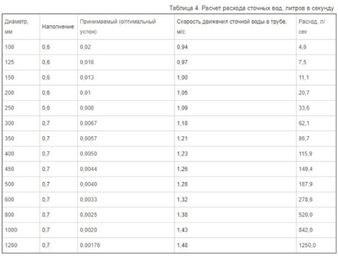
As a rule, only the last two parameters are calculated during calculations - the rest after that can be determined without any problems. The amount of hydraulic slope is usually equal to the slope of the ground, which will allow the flow of water to move at the speed necessary for the system to self-clean.
The speed and maximum filling level of domestic sewage are determined by the table, which can be written as follows:
- Diameter 150-250 mm - h / DN is 0.6, and the speed is 0.7 m / s.
- Diameter 300-400 mm - h / DN is 0.7, speed - 0.8 m / s.
- Diameter 450-500 mm - h / DN is 0.75, speed - 0.9 m / s.
- Diameter 600-800 mm - h / DN is 0.75, speed - 1 m / s.
- Diameter 900+ mm - h / DN is 0.8, speed - 1.15 m / s.
For a product with a small cross section, there are normative indicators for the minimum slope of the pipeline:
- With a diameter of 150 mm, the slope should not be less than 0.008 mm;
- With a diameter of 200 mm, the slope should not be less than 0.007 mm.
The following formula is used to calculate the volume of wastewater:
- q = a*v,
Where a is the free area of the flow;
v is the speed of effluent transportation.

The rate of transport of a substance can be determined using the following formula:
- v=C√R*i,
where R is the value of the hydraulic radius,
C is the wetting coefficient;
i - the degree of slope of the structure.
From the previous formula, the following can be deduced, which will allow you to determine the value of the hydraulic slope:
- i=v2/C2*R.
To calculate the wetting coefficient, a formula of the following form is used:
- С=(1/n)*R1/6,
Where n is a coefficient that takes into account the degree of roughness, which varies from 0.012 to 0.015 (depending on the pipe material).
The R value is usually equated to the usual radius, but this is only relevant if the pipe is completely filled.
For other situations, a simple formula is used:
- R=A/P
Where A is the cross-sectional area of the water flow,
P is the length of the inner part of the pipe that is in direct contact with the liquid.
Tabular calculation of sewer pipes
It is also possible to determine the patency of the pipes of the sewer system using tables, and the calculations will directly depend on the type of system:
- Non-pressure sewerage. To calculate non-pressure sewer systems, tables are used that contain all the necessary indicators. Knowing the diameter of the installed pipes, you can select all other parameters depending on it and substitute them into the formula. In addition, the table indicates the volume of liquid passing through the pipe, which always coincides with the pipeline's permeability. If necessary, you can use the Lukin tables, which indicate the throughput of all pipes with a diameter in the range from 50 to 2000 mm.
- Pressure sewer. It is somewhat easier to determine the throughput in this type of system using tables - it is enough to know the maximum degree of filling of the pipeline and the average speed of liquid transportation.

Bandwidth table polypropylene pipes allows you to find out all the parameters necessary for arranging the system.
Calculation of the capacity of the water supply
Water pipes in private construction are used most often. In any case, the water supply system has a serious load, so the calculation of the throughput of the pipeline is mandatory, because it allows you to create the most comfortable operating conditions for the future structure.
To determine the patency water pipes you can use their diameter. Of course, this indicator is not the basis for calculating the patency, but its influence cannot be ruled out. The increase in the inner diameter of the pipe is directly proportional to its permeability - that is, a thick pipe almost does not impede the movement of water and is less susceptible to the accumulation of various deposits.

However, there are other indicators that also need to be taken into account. For example, a very important factor is the coefficient of friction of the liquid on the inside of the pipe (for different materials have eigenvalues). It is also worth considering the length of the entire pipeline and the pressure difference at the beginning of the system and at the outlet. An important parameter is the number of different adapters present in the design of the water supply system.
The throughput of polypropylene water pipes can be calculated depending on several parameters tabular method. One of them is a calculation in which the main indicator is the temperature of the water. As the temperature rises, the liquid expands in the system, so friction increases. To determine the patency of the pipeline, you need to use the appropriate table. There is also a table that allows you to determine the patency in the pipes depending on the water pressure.

The most accurate calculation of water according to the throughput of the pipe is made possible by the Shevelev tables. In addition to accuracy and a large number of standard values, these tables contain formulas that allow you to calculate any system. This material fully describes all situations related to hydraulic calculations, therefore, most professionals in this field most often use the Shevelev tables.
The main parameters taken into account in these tables are:
- External and internal diameters;
- Pipeline wall thickness;
- The period of operation of the system;
- The total length of the highway;
- Functional purpose of the system.
Conclusion
Pipe capacity calculation can be done in different ways. The choice of the optimal calculation method depends on a large number of factors - from the size of the pipes to the purpose and type of system. In each case, there are more and less accurate calculation options, so both a professional specializing in laying pipelines and an owner who decides to independently lay a highway at home will be able to find the right one.