
Hydraulic resistance of pipelines calculator. Throughput capacity of pipes of different diameters and materials
Calculation of water pressure losses in the pipeline is performed very simply, further we will consider in detail the calculation options.
For hydraulic calculation pipeline, you can use the pipeline hydraulic calculation calculator.
Have you been lucky enough to drill a well right next to your house? Wonderful! Now you can provide yourself and your house or cottage with clean water, which will not depend on the central water supply. And this means no seasonal shutdown of water and running with buckets and basins. All you have to do is install the pump and you're done! In this article, we will help you calculate the pressure loss of water in the pipeline, and already with these data, you can safely buy a pump and finally enjoy your water from the well.
It is clear from school physics lessons that water flowing through pipes experiences resistance in any case. The value of this resistance depends on the flow velocity, the diameter of the pipe and the smoothness of its inner surface. The resistance is the smaller, the lower the flow velocity and the larger the diameter and smoothness of the pipe. Pipe smoothness depends on the material from which it is made. Pipes made of polymers are smoother than steel pipes, and they also do not rust and, importantly, are cheaper than other materials, while not inferior in quality. Water will experience resistance, even moving along a completely horizontal pipe. However, the longer the pipe itself, the less significant the pressure loss will be. Well, let's start the calculation.
Head loss in straight pipe sections.
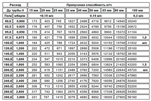
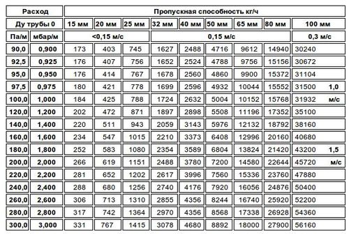
To calculate the loss of water pressure in straight sections of pipes, he uses a ready-made table, presented below. The values in this table are for pipes made from polypropylene, polyethylene and other words beginning with "poly" (polymers). If you are going to install steel pipes, then it is necessary to multiply the values \u200b\u200bgiven in the table by a factor of 1.5.
Data are given for 100 meters of pipeline, losses are indicated in meters of water column.
|
Consumption |
Pipe inner diameter, mm |
||||||||||
How to use the table: For example, in a horizontal water pipe with a pipe diameter of 50 mm and a flow rate of 7 m 3 / h, the loss will be 2.1 meters of water column for a polymer pipe and 3.15 (2.1 * 1.5) for a steel pipe. As you can see, everything is quite simple and clear.
Head loss due to local resistances.
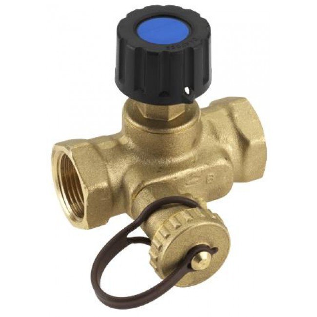
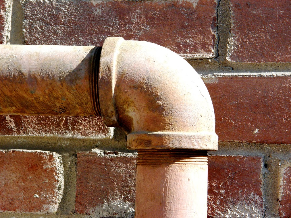
Unfortunately, pipes are absolutely straight only in a fairy tale. In real life, there are always various bends, dampers and valves that cannot be ignored when calculating the pressure loss of water in a pipeline. The table shows the head loss values for the most common local resistances: 90 degree elbow, rounded elbow and valve.
Losses are given in centimeters of water column per unit of local resistance.
|
Flow velocity, m/s |
Elbow 90 degrees |
Rounded knee
|
Valve
|
To determine v - flow rate it is necessary Q - water consumption (in m 3 / s) divided by S - cross-sectional area (in m 2).
Those. with a pipe diameter of 50 mm (π * R 2 \u003d 3.14 * (50/2) 2 \u003d 1962.5 mm 2; S \u003d 1962.5 / 1,000,000 \u003d 0.0019625 m 2) and a water flow rate of 7 m 3 / h (Q \u003d 7 / 3600 \u003d 0.00194 m 3 / s) flow rate
v=Q/S=0.00194/0.0019625=0.989 m/s
As can be seen from the above data, pressure loss at local resistances quite insignificant. The main losses still occur in horizontal sections of pipes, therefore, in order to reduce them, carefully consider the choice of pipe material and their diameter. Recall that in order to minimize losses, it is necessary to choose pipes made of polymers with a maximum diameter and smoothness of the inner surface of the pipe itself.
Bandwidth pipes is the ratio of the volume of liquid, gas or air that can pass through a pipe of a certain diameter per unit time.
Simply put, this indicator is needed for the correct installation of the pipeline, taking into account the provision of all water intake points (bathroom, kitchen, washing machine, water supply, etc.) with adequate water pressure after startup.
Correct calculation and is the key to a reasonable investment of money and a guarantee of the smooth functioning of the pipeline system. All calculations can be carried out by contractors or independently.
If the repair is done by hand, there will be a need to delve deeper into the topic, study publicly available materials, and only then choose them.
Several methods are used to calculate the indicator:
- Calculator-program - publicly available programs in which you need to enter the initial data.
- Engineering formulas - a professional level that takes into account many nuances, most often this calculation method is used in large-scale design.
- Pivot tables - use already entered data and indicators, choosing those that are closer to the original situation.
Even public spreadsheets and calculators will need some data.
What data is required:

- Pipe material.
- Pipeline length.
- and its form.
- The number of liquid sampling points.
- Structural slope.
- Presence of systemic pressure.
- Mounting method.
For more accurate calculation you have to take into account all the individual nuances. There are no universal methods, for many projects it is necessary to take into account the roughness coefficient of pipes, resistance to water flow, and the rate of "overgrowth".
Pipe diameter can be called the most important indicator in the calculations. If the system is mounted from pipes of a smaller diameter than necessary, this leads to a number of unpleasant moments.
- Increased load and pressure in the system leads to rapid wear of the system, frequent breakthroughs and repairs.
- The “humming” of the system is extraneous noise injected by excessive pressure on the pipe walls.
- The impossibility of simultaneous water intake from several points - in other words, when you open a tap at one point, for example, in a bathroom, the water no longer reaches.
- The maximum possible water velocity in the pipe is 2 m/s. This condition does not apply to industrial structures with installations that artificially build up internal system pressure.
- When calculating, take into account the consumption of all points of water intake at the same time. The average throughput is 6 l / s, the set speed of the washing machine or dishwasher can be found in the instruction manual. If the system is not used at full intensity, then the resulting figure is reduced by a third.

- Diameter 20 mm - for plumbing systems up to 10 meters long.
- Diameter 25 mm - system from 10 to 30 meters.
- Diameter 32 mm - system over 30 meters.
- Diameter 50 mm - system over 50 meters.
- Diameter 100 mm - used in industrial or long piping systems with a large number of water intake points.
The next important indicator is the pressure of the system. When installing a gravity water supply system, smaller diameters are allowed. If pressure is constantly present in the system, for example, city water supply, its indicator must be taken into account when calculating. If this indicator is ignored, the pipes will “buzz” and vibrate, which will lead to deformation of the connecting adhesions and disable the system.
If he talks about metal, then steel pipes are also used for plumbing. For intra-apartment or intra-house wiring, formulas and special calculations are used extremely rarely.
More often use proven diameters:
- Plumbing 15 mm.
- Installation of risers 25, 32, 40 mm.
Here you need to take into account the inner diameter, which can vary by 1-3 mm, depending on the manufacturer.
The new one is practically not inferior in performance to plastic counterparts, but after a year its throughput drops significantly. This is due to the appearance of growths on the inner walls, and, as a result, a decrease in diameter and an increase in resistance to water flow.
However, the use metal pipes justified when it comes to permanent high pressure systems, e.g. during installation steam heating, industrial projects or in high explosive environments.
Progressive manufacturers every year bring to the market more convenient and high-quality materials, optimizing their characteristics to the requirements of the consumer.
There are pipes from:
- Polyethylene and cross-linked polyethylene (PEX).
- Metal polymers or metal-plastic - a combination of PEX with metal.
- Polyvinyl chloride (PVC).
- Polypropylene (PP) and its varieties, depending on.
As for the throughput of pipes made of these materials, it is much higher than that of pipes made of metal, given the service life. All of the above types of pipes have significant advantages over metal ones.
- Durability - if used correctly, the service life plastic pipes can reach 50 years, the metal needs to be replaced after a maximum of 20 years of use.
- The smooth inner surface of the pipes - the original characteristics and inertness of the polymers do not allow the system to overgrow, are not damaged in the presence of mechanical particles in the water, are not susceptible to corrosion and aggressive chemicals.
- Ease of installation and repair - the light weight of the structure and a collapsible fitting allow you to cope with the maintenance of the network yourself.
- Significant savings - plastic materials and their transportation is several times cheaper compared to metal.
The only drawback is that they do not withstand long-term operation at a pressure of more than 10 atmospheres and extremely high temperatures.
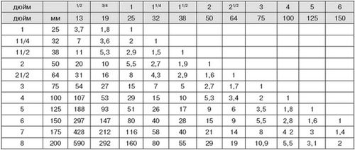
To calculate the throughput of a new pipe, regardless of the material of manufacture, the following table can be used: 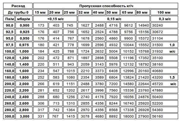
In this article we will solve the problem of pressure loss in the pipeline. This article will help you understand how flow resistance works. On real numbers, I will describe the algorithm how to do it. We use basic formulas.
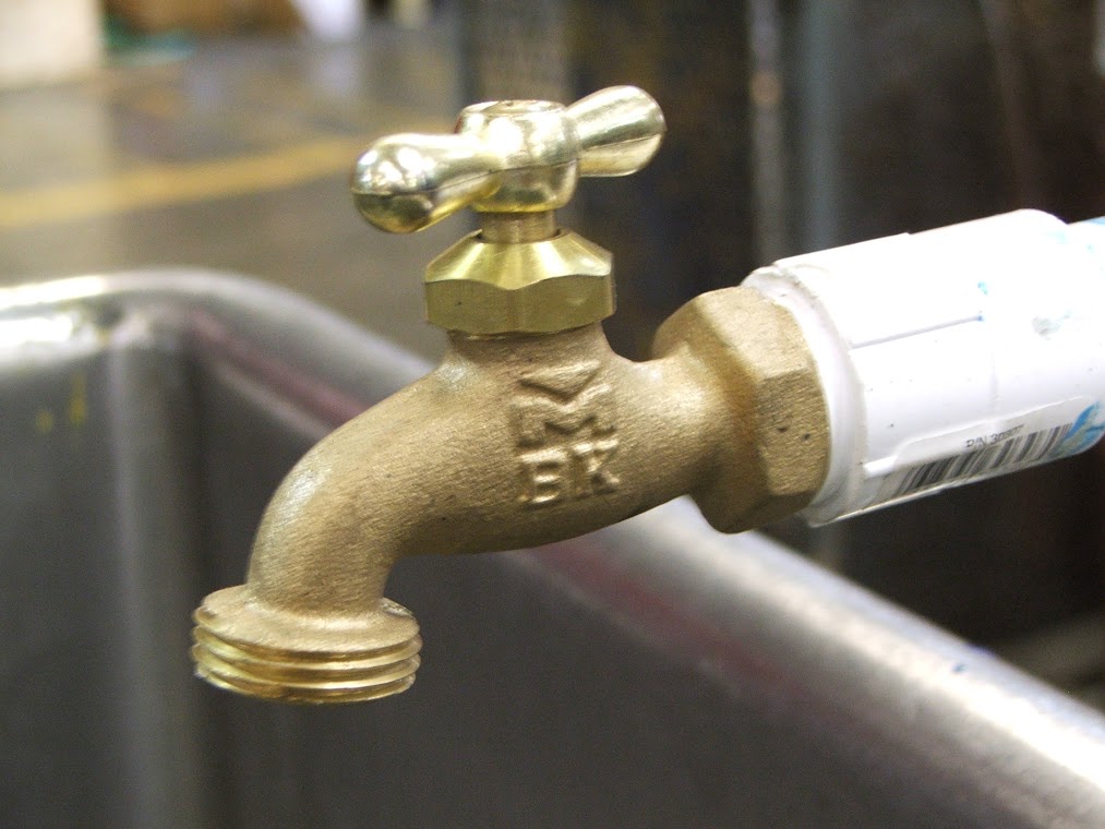
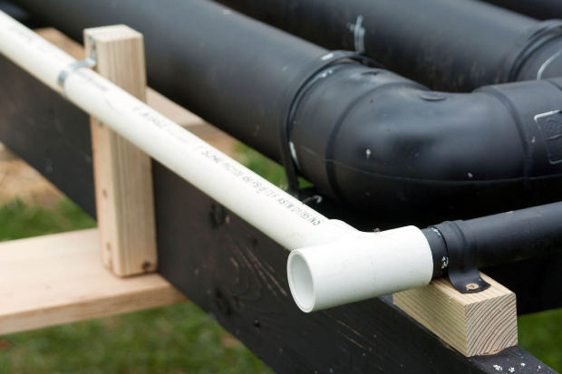
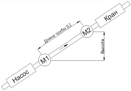
Let's analyze a simple example with a pipe, as you can see in the image at the beginning of the pump, then there is a pressure gauge, which allows you to measure the pressure of the liquid at the beginning of the pipe. After a certain length, a second pressure gauge is installed, which allows you to measure the pressure at the end of the pipe. Well, at the very end is a crane. This scheme is quite simple, and I will try to give examples. So, let's begin.
In general, there is more than one way to find out the pressure loss: A method when the pressure at the beginning and at the end is known, you can calculate the pressure loss using the formula: M1-M2=Pressure, that is, this difference between the two gauges. Let's say we got, roughly speaking, 0.1 MPa, which is one atmosphere. This means that we have a loss of pressure along the length of 0.1 MPa. Please note that we can indicate the head loss in two values, this is the hydrostatic pressure, which is 0.1 MPa and the height of the water column in meters, which is 10 meters. As I have said more than once, every 10 meters is one atmosphere of pressure.
There is a good formula that allows you to calculate the head loss along the length of the pipeline.
![]()
Now let's talk about the coefficient of hydraulic friction.
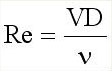
The formula for finding this coefficient depends on the Reynolds number and the equivalent pipe roughness.
Let me remind you of this formula (it only applies to round pipes):
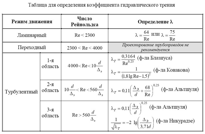
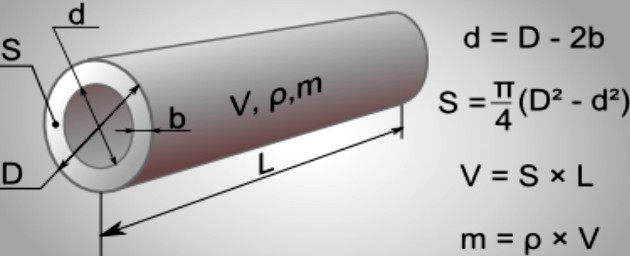
Here Δ e- Equivalent to pipe roughness. This value in the tables is indicated in millimeters, but when you insert it into the formula, be sure to translate it into meters. In general, do not forget to observe the proportionality of units of measurement and do not mix [mm] with [m] in formulas of different types.
d is the inner diameter of the pipe, that is, the diameter of the fluid flow.
I also want to note that similar roughness values are absolute and relative, or even there are relative coefficients. Therefore, when you look for tables with values, then this value should be called "roughness equivalent" and nothing else, otherwise the result will be erroneous. Equivalent means - the average height of the roughness.
In some cells of the table, two formulas are indicated, you can count on any selected one, they almost give the same result.
In general, in general, these formulas show and prove that with an increase in speed or an increase in flow, the resistance to the movement of fluid flow always increases, that is, head losses increase. Moreover, they increase not proportionally, but quadratically. This suggests that the unit of increase in flow does not correspond to the cost of head loss. That is, it is not economically feasible to have a high fluid flow rate in the pipe. Therefore, it is cheaper to increase the flow diameter. In other articles I will definitely describe how to calculate what diameter we need.
Table: (Roughness Equivalent)
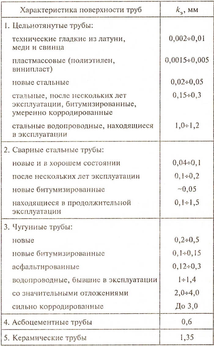
Who is interested to know Roughness equivalent) for metal-plastic, polypropylene and cross-linked polyethylene, then this corresponds and applies to plastics. That is, in the table the characteristic will be: Plastic (polyethylene, vinyl plastic).
I also want to draw attention to the fact that over time, plaque forms on the internal machine tools of the pipes, which increases the roughness of the pipes. So keep in mind that over time, head loss only increases.
Table: ( Kinematic viscosity of water)
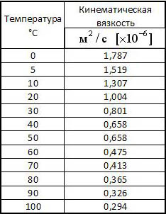
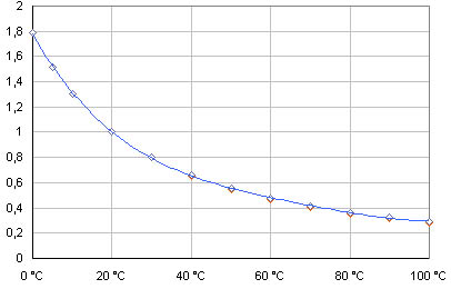
As can be seen from the graph, as the temperature rises, the kinematic viscosity decreases, which means that the resistance to water movement also decreases. This means that with a flow of hot water, the "pressure loss" will be less than with a flow cold water. Who lives in apartment buildings, if you pay attention, then the speed and pressure of hot water is always higher than the pressure of cold water. There are exceptions, but in most cases this is the case. Now you understand why this is so.
Now let's solve the problem:
Find the pressure loss along the length when water moves through a new cast-iron pipe D=500mm at a flow rate Q=2 m 3 /s, pipe length L=900m, temperature t=16°C.
Solution: First, let's find the flow velocity in the pipe using the formula:
Here ω - cross-sectional area of the flow. It is found according to the formula:
ω \u003d πR 2 \u003d π (D 2 / 4) \u003d 3.14 * (0.5 2 / 4) \u003d 0.19625 m 2
Re=(V*D)/ν=(10.19*0.5)/0.00000116=4 392 241
ν \u003d 1.16 * 10 -6 \u003d 0.00000116. Taken from the table. For water at 16°C.
Δ e \u003d 0.25 mm \u003d 0.00025 m. Taken from the table, for new cast iron.
λ=0.11(Δe/D) 0.25=0.11*(0.00025/0.5) 0.25=0.01645
![]()
h \u003d λ * (L * V 2) / (D * 2 * g) \u003d 0.01645 * (900 * 10.19 2) / (0.5 * 2 * 9.81) \u003d 156.7 m.
Answer: 156.7 m = 1.567 MPa.
I also want to draw attention to the fact that in the problem we considered a pipe that has a horizontal position along its entire length.
Let's look at an example where the pipe goes up at a certain angle.
In this case, we need to add the height (in meters) to the head loss to the usual task. If the pipe will go downhill, then you need to subtract the height.
We considered the pressure loss along the length of the pipeline, also exist in the form of narrowing and turns, which also affect the pressure loss. They will be described in my other articles. And I will definitely prepare an article on how to meet the requirements of the flow rate, depending on the head loss. If something is not clear, write in the comments, I will definitely answer!
| If you wish to receive notifications about new useful articles from the section: Plumbing, water supply, heating, then leave your name and email. |
||
| Comments(+) [ Read / Add ] |
The throughput of a water pipe is one of the basic parameters for the calculation and design of pipeline systems designed to transport hot or cold water in the water supply, heating and sanitation system. It is a metric value showing how much water can flow through a pipe in a given period of time.
The main indicator on which the throughput of a pipe depends is its diameter: the larger it is, the correspondingly more water can pass through it in a second, minute or hour. The second most important parameter that affects the amount and speed of water passage is the pressure of the working medium: it is also directly proportional to the throughput of the pipeline.
What other indicators determine the throughput of the pipeline?
These two basic parameters are the main, but not the only values on which the throughput depends. Other direct and indirect conditions that affect or may potentially affect the speed of passage of the working medium through the pipe are also taken into account. For example, the material from which the pipe is made, as well as the nature, temperature and quality of the working environment also affect how much water can pass through the pipe in a given period of time.
Some of them are stable indicators, while others are taken into account depending on the life and duration of the operation of the pipeline. For example, if we are talking about a plastic pipeline, then the speed and amount of water passage remains constant throughout the entire period of operation. But for metal pipes through which water flows, this indicator decreases over time for a number of objective reasons.
How does the material of a pipe affect its capacity?
Firstly, the corrosion processes that always occur in metal pipelines contribute to the formation of a persistent rust coating, which reduces the diameter of the pipe. Secondly, poor water quality, especially in the heating system, also significantly affects the flow of water, its speed and volume.
AT hot water Central heating systems contain a large amount of insoluble impurities that tend to settle on the surface of the pipe. Over time, this leads to the appearance of a solid precipitate of hardness salts, which quickly reduce the lumen of the pipeline and reduce the throughput of pipes (you could often see examples of rapid overgrowth of pipes in the photo on the Internet).
The length of the contour and other indicators that must be taken into account when calculating
Another important point to consider when calculating the throughput of a pipe is the length of the circuit and the number of fittings (couplings, stopcocks, flange parts) and other obstacles in the way of the working medium. Depending on the number of corners and bends that water overcomes on its way to the exit, the throughput of the pipeline also tends to increase or decrease. The length of the pipeline directly also affects this basic parameter: the longer the working medium moves through the pipes, the lower the water pressure and, accordingly, the lower the throughput.
How is pipe capacity calculated today?
All these values can be correctly used during calculations using a special formula that is used only by experienced engineers, taking into account several parameters, including those listed above, as well as several others. Let's call it all:
- roughness of the inner walls of the pipeline;
- pipe diameter;
- resistance coefficient when passing through obstacles in the way of water;
- pipeline slope;
- the degree of overgrowth of the pipeline.
According to the old engineering formula, pipe diameter and throughput are the main parameters for calculation, to which roughness is added. But it is difficult for a non-specialist to perform calculations based only on these data. Previously, to simplify the task when designing a water supply and heating system, special tables were used, in which ready-made calculations of the required indicator were given. Today, they can also be used for pipeline design.
Old calculation tables - a reliable guide for the modern engineer
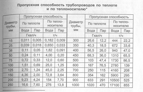
Old Soviet books on repair, as well as magazines and construction, often published tables with calculations that are very accurate, because. were derived from laboratory tests. For example, in the pipe capacity table, the value for a pipe with a diameter of 50 mm is 4 t / h, for a pipe of 100 mm - 20 t / h, for a pipe of 150 mm - 72.8 t / h, and for Te. it can be understood that the throughput of the pipe, depending on the diameter, does not change according to arithmetic progression, but according to another formula, which includes various indicators.
Online calculators are also helpful
Today, in addition to the complex shape and ready-made tables, the calculation of the throughput of the pipeline can be done using special computer programs, which also use the above options to be entered into the computer.
A special calculator for calculation can be downloaded on the Internet, as well as use various online resources, of which there are a great many on the Web today. They can be used both on a paid and free basis, but many of them may have inaccuracies in the formulas for calculations and are difficult to use.
For example, some calculators suggest using either the diameter / length ratio or the roughness / material as the basic parameters. To know the roughness index, you also need to have special knowledge from the field of engineering. The same can be said about the pressure drop, which is used by the online calculator in the calculations.
If you do not know where to find out or how to calculate these parameters, then it is better for you to seek help from specialists, or use an online calculator to calculate the throughput of a pipe.
8.6 Calculation of pipelines for nozzle lines, skimmers, bottom drain.
Now we will select the diameters of the pipelines with which we will tie the nozzles and skimmers. For calculations, we will use the following table:
Table 8.4. Throughput of pipes of various diameters.
|
Diameter |
Square |
Pass. capacity at speed, m3/h |
||||||||
|
outer, mm |
int., mm |
internal section, mm2 |
||||||||
|
0.5 m/s - water velocity in the pipe from the overflow tray |
||||||||||
|
0.8 m/s - water velocity in the collector pipe |
||||||||||
|
1.2 m/s - water velocity in the pipe at the pump inlet |
||||||||||
|
2.0 m/s - the speed of the water at the exit of the pump |
||||||||||
|
2.5 m / s - the maximum possible speed of water in the pipe |
||||||||||
This table provides an opportunity to calculate pipe diameters in different structural applications and different required performance:
Pipe diameters from the overflow tray to the collector;
Collector pipe diameters;
Diameters of the suction pipe for supply to the pump;
The diameter of the pipe after the pump, filters, nozzle lines.
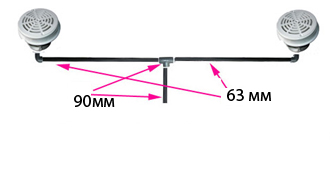
We have 4 nozzles in the pool and a pump with a capacity of 15m 3 / h. Those. each nozzle accounts for almost 4m 3 /h. Based on the performance of the pump, according to the table, we will select a common supply pipe to the nozzles. We take the speed of water in the pipe as 2 m / s and find the value of the pipe diameter at 15m 3 / h. If there is no exact value in the table, then we take the nearest one. In our case, the supply pipe to the nozzles will be 63 mm in diameter, and the branches to the pairs of nozzles will be 50 mm in diameter.
Figure 8.11. Injector line connection.
To connect the nozzles, we need the following materials:
Corner 50mm-90 0 - 6 pcs.
Tee 50mm - 2 pcs.
Tee 63mm - 1 pc.
Reduction short 63-50mm - 2 pcs.
-pipe 63mm - 6 m. (Determined by the distance from the center
long side to the technical room.)
Pipe 50mm - 12m. (summing up all pipe segments 50mm
according to the calculated position of the injectors.)
To connect the bottom drain, a pipe with a diameter is usually sufficient, as is the diameter of the outlet of the bottom drain itself (for private pools this is 2"" and, accordingly, a pipe D = 63mm). If there are two bottom drains, then they must be connected into a pipe D = 90mm.
Rice. 8.12 Connecting bottom drains.
In our case, there is only one bottom drain. Therefore, to connect it, the following materials are sufficient:
Clutch N.R. 63-2"" - 1 pc.
Pipe 63mm - 2m.
Now let's determine which pipe the skimmer is connected to. Skimmers usually have holes with 1.5"" or 2"" connections. The skimmer in the pool in filtration mode takes about 70-90% of the total flow that the pump sucks in, and the rest falls on the bottom drain. Therefore, it is necessary to navigate by the plate. We look at the graph with a flow rate of 1.2 m / s (the speed of the water at the pump inlet) and select the diameter of the pipe with a capacity of 15m 3 / h-30% \u003d 10m 3 / h. In our case, a pipe with a diameter of D \u003d 63mm will be enough, but it would be ideal to put a pipe D \u003d 75mm.
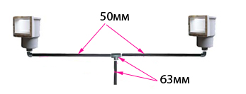
Figure 8.13 tying the skimmers.
To tie the skimmers, we need the following materials:
Clutch N.R. 50-2"" - 2 pcs.
Angle 50-90 0 - 2 pcs.
Tee 63 - 1 pc.
Reduction 63-50 - 2 pcs.
Pipe 50mm - 6m.