Steam heating in an apartment building. Steam heating
K category: Water heating
Steam heating systems
The process of converting water into steam is divided into two stages. In the first stage, heat is supplied to the water in the amount necessary to bring its temperature to a boil, which increases with increasing pressure. In the second stage, water heated to the boiling point is supplied with heat in the amount necessary for its evaporation. This amount of heat decreases with increasing pressure. The heat expended on evaporation is spent on the splitting of water molecules and on its volumetric expansion, without causing an increase in the temperature of either water or steam. This heat is called the heat of vaporization.
Thus, the total heat of dry saturated steam is equal to the sum of the heat spent on heating the liquid to the boiling point and the heat of vaporization.
At a pressure of 1.1 atm, the boiling point of water is 100.8 °C. The heat of vaporization in this case is 539.1 kcal/kg.
If the heat of vaporization is taken away from the steam, then the steam turns into water - it condenses. The temperature of the condensate is equal to the temperature of the steam, but the heat content of the condensate will only be equal to the amount of heat expended in bringing the liquid to the boiling point.
The specified property of steam during condensation - to release the heat of evaporation - is used in heating systems.
Steam systems low pressure can be made with top and bottom steam distribution. They can be two-pipe and one-pipe. The latter, due to a number of operational shortcomings, were not widely used.
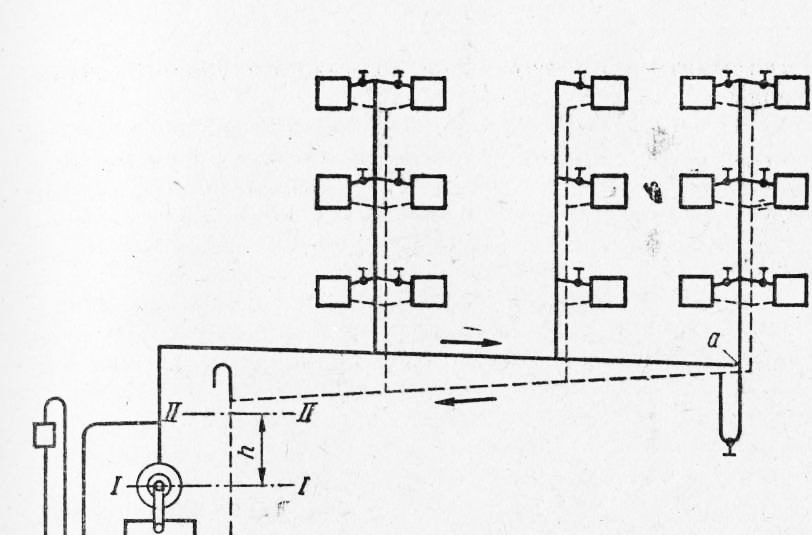
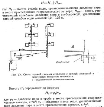
On fig. 1 shows the circuit steam heating low pressure with top wiring and dry condensate piping.
Due to the difference in steam pressure in the boiler and at the heating device, steam from the boiler through the main riser and then through the steam line and steam risers enters the heating devices equipped with a steam valve. Steam condenses in heaters. The resulting condensate is returned to the boiler by gravity through the condensate risers and the condensate collection line.
For normal operation of the system, a free exit to the atmosphere of air is necessary, with which pipelines and devices are filled before the system is started. This air is displaced by steam pressure from the steam pipelines to the heating devices, from where, together with the condensate, it enters the condensate pipeline.
Through an open vent pipe installed at a point that serves as a central place for removing air from the system, the condensate pipeline communicates with the atmosphere.
In order for air to be vented through the condensate piping, two conditions must be met:
1) the sections of the condensate pipeline must be such that the condensate does not completely fill them and that they also have a free section above the water for the placement and movement of air;
2) water must not be forced out of the boiler into the condensate pipeline both during the operation of the system and during its shutdown. To do this, the condensate pipeline must be laid high, above the possible level of standing water (level II-II in Fig. 1).
When the system is not in operation, the water in the boiler and vertical section of the condensate pipe is at level I-I. When the system is started, under the influence of steam pressure on the water surface, the latter in the boiler and in the vertical section of the condensate pipeline rises to level II-II.
The difference between levels II-II and I-I, denoted by the letter h in the figure, is determined by the magnitude of the vapor pressure, since this column of water balances this pressure.
For example, at a steam pressure in the boiler of 0.2 atm, the height h is 2 m. 200-250 mm. Since under these conditions the condensate line 6 will not be filled with water, it is called the “dry” condensate line. With this scheme, all heating devices, in order to avoid filling them with condensate, should be placed above the condensation line.
In the event that, for a number of reasons, the heating devices have to be located at a slight height above the boiler or at the same level with it, an open circuit for returning condensate to the boiler is used.
Rice. 1. Low pressure steam heating system with top wiring
In this case, the condensate flows by gravity first into the collection condensate tank, from where it is pumped to the boiler by means of a pump. The condensate line up to the tank also serves in this case as an air outlet and operates with an unfilled section. Air is vented to the atmosphere through a condensing tank.
To prevent water from being squeezed out of the boiler into the condensate tank when the pump is stopped, a check valve is installed in front of the latter, allowing water to pass only from the side of the boiler.
In steam lines through which steam moves from the boiler to the heating devices due to the heat transfer of pipelines in environment, There is some condensation of steam. The largest amount of condensate is released when the system is started after a break, during which the pipelines are very cool. In order to avoid the occurrence of water locks, and thereby hydraulic shocks, the specified condensate must be well discharged from the steam pipelines to the condensate pipelines through heating devices. To do this, steam lines must be laid with a slope of 0.005 towards the movement of steam, and condenser lines with the same slope towards the boiler.
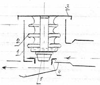
Rice. 2. Scheme of low pressure steam heating with dry condensate line and bottom wiring
On fig. 2 shows a diagram of steam heating with a dry condensate line and bottom wiring. Structurally, it differs from the scheme with the upper wiring only in the position of the steam line. To drain the condensate formed in the steam line, the latter at point a is connected to the condensate line through a special loop.
The loop is a V-shaped hydraulic lock, in which, during the operation of the system, the difference in the heights of the water columns h is maintained, balancing the steam pressure at the point of attachment of the loop to the steam line. Due to this, steam from the line cannot enter the condensate line. In the case of a direct connection of the steam line to the condensate line, steam would break into it, which would lead to water hammer and significant unproductive loss of steam.
A steam heating scheme with a “wet” condensate line and an upper wiring is also used. These systems include those in which the condensate lines are completely filled with water and do not have an air tank for air removal.
A scheme of a steam heating system with a “wet” condensate line and with a lower wiring is also used. In this case, a loop device is not required to drain the condensate formed in the steam line, since the condensate risers themselves are filled with condensate to a level that ensures the presence of a hydraulic seal that prevents steam from penetrating into the condensate line.
Of the systems considered, the most economical are systems with a lower steam distribution, since they reduce the length of the risers, and the total length of the pipelines is less than with the upper wiring.
The lower wiring is also more profitable than the upper one in terms of heat loss by pipelines. With the upper wiring, these losses are greater, since the steam line is usually laid in the attic. With the lower wiring, the heat transfer of the main is used for heating buildings.
Along with this, the upper wiring has some operational advantages over the lower one. With top wiring, there is no need for loops that require periodic cleaning of dirt. The system with the top wiring is silent, because throughout the entire length of the pipelines, with the exception of the main riser, the condensate formed in the steam lines moves in the same direction as the steam. In systems with lower wiring, the condensate formed in the steam risers moves towards the steam, which can cause water hammer and noise in the system.
The question of choosing a "wet" or "dry" condensate pipeline is decided depending on local conditions. At the same time, it should be borne in mind that with a “dry” condensate pipeline, there is no need to lay an air line, but the diameters of the condensate pipeline itself are somewhat larger than those of a “wet” one, since they also serve to remove air.
Condensate lines are more susceptible to rusting (corrosion) than other parts of systems. Since a “wet” condensate line is completely filled with water, it is less susceptible to corrosion than a “dry” one, which carries both water and air.
Steam heating systems high pressure perform with upper and lower steam wiring.
Typically, high-pressure steam systems are supplied from common factory boilers, which also serve technological needs. For heating, steam with a pressure of no higher than 2-3 atm is most often used. If steam is supplied from the boiler room at a higher pressure than is required for heating, then a pressure reducing valve is installed - a device with which the steam pressure can be reduced to the required value.
The condensate from the system goes to the condensate tank, from where centrifugal pump pumped into boilers.
During the operation of heating systems, the temperature of the pipeline becomes approximately equal to the temperature of the coolant, and during breaks the pipeline cools down.
Temperature fluctuations cause expansion and contraction of pipes. With large pipeline lengths and large temperature fluctuations that occur in steam heating systems, the change in the length of the pipes becomes significant, therefore, in order to avoid rupture of pipelines, it is necessary to use special devices, the so-called compensators. In domestic water systems, in which temperature fluctuations are not higher than 60-70 ° C and where the length of straight sections is small and there are many turns and corners, compensators are usually not used, and compensation is carried out due to slight deformation of the pipes in the corners and in places of turns.
The greatest application in steam systems and in water systems with water temperatures above 95 ° C are U-shaped expansion joints bent from pipes, installed on straight sections of pipelines between two dead points, i.e., two supports that fix the pipeline motionlessly.
To avoid the accumulation of condensate or air in them, bent expansion joints are installed in a horizontal position parallel to the axis of the pipe.
Steam heating systems
If you heat water in an open vessel at atmospheric pressure, then its temperature will continuously increase until the entire mass of water warms up and boils. In the process of heating, the evaporation of water occurs from its open surface, when boiling, steam from water is formed on the heated surface and partially in the entire volume of the liquid. At the same time, the water temperature remains constant (equal to about 100 °C in the case under consideration), despite the continuous supply of heat to the vessel from outside. This phenomenon is explained by the fact that during boiling, the heat supplied is spent on the work of splitting water particles and forming steam from them.
When water is heated in a closed vessel, its temperature also rises only until the water boils. The steam released from the water accumulates in the upper part of the vessel above the surface of the water level; its temperature is equal to the temperature of boiling water. Such steam is called saturated.
If steam is not removed from the vessel, and the supply of heat to it (from outside) continues, then the pressure in the entire volume of the vessel will increase. As the pressure increases, so does the temperature of the boiling water and the steam formed from it. It has been experimentally established that each pressure has its own temperature of saturated steam and the boiling point of water equal to it, as well as its own specific volume of steam.
So, at atmospheric pressure (0.1 MPa), water begins to boil and turns into steam at a temperature of about 100 ° C (more precisely, at 99.1 ° C); at a pressure of 0.2 MPa - at 120 °C; at a pressure of 0.5 MPa - at 151.1 ° C; at a pressure of 10 MPa - at 310 °C. From the above examples, it can be seen that with increasing pressure, the boiling point of water and its equal temperature of saturated steam increase. The specific volume of steam, on the contrary, decreases with increasing pressure.
At a pressure of 22.5 MPa, the heated water passes into saturated steam instantly, so the latent heat of vaporization at this pressure is zero. A vapor pressure of 22.5 MPa is called critical.
If saturated steam is cooled, it will begin to condense, i.e. will turn into water; at the same time, it will give up its heat of vaporization to the cooling body. This phenomenon takes place in steam heating systems, in which saturated steam comes from a boiler room or a steam line. Here it is cooled by the air of the room, gives off its heat to the air, due to which the latter heats up, and the steam condenses.
The state of saturated steam is very unstable: even small changes in pressure and temperature lead to the condensation of part of the steam or, conversely, to the evaporation of water droplets present in saturated steam. Saturated steam, completely free of water droplets, is called dry saturated; Saturated steam with water droplets is called wet steam.
As a heat carrier in steam heating systems, saturated steam is used, the temperature of which corresponds to a certain pressure.
Steam heating systems are classified according to the following criteria:
According to the initial steam pressure - low pressure systems (p< 0,07 МПа);
Condensate return method - systems with gravity return (closed) and with condensate return using a feed pump (open);
Structural scheme of laying pipelines - systems with upper, lower and intermediate laying of distribution steam pipelines, as well as with laying of dry and wet condensate pipelines.
A diagram of a low-pressure steam heating system with an upper steam line is shown in fig. 1, a. The saturated steam generated in the boiler 1, having passed the dry steamer (separator) 12, enters the steam line 5 and then enters heating appliances 7. Here, the steam gives off its heat through the walls of the devices to the air of the heated room and turns into condensate. The latter flows down the return condensate pipeline 10 into the boiler 1, while overcoming the steam pressure in the boiler due to the pressure of the condensate column, which is maintained at a height of 200 mm in relation to the water level in the dry steamer 12.
Figure 1. Low pressure steam heating system: a - scheme of the system with the upper laying of the steam pipeline; b - riser with lower steam wiring; 1 - boiler; 2 - hydraulic shutter; 3 - water gauge glass; 4 - air tube; 5 - supply steam pipeline; 6 - steam valve; 7 - heater; 8 - tee with a plug; 9 - dry condensate pipeline; 10 - wet condensate line; 11 - make-up pipeline; 12 - dry steamer; 13 - bypass loop
A tube 4 is mounted in the upper part of the return condensate pipeline 10, connecting it with the atmosphere for purge at the time of commissioning and decommissioning the system.
The water level in the steamer is controlled using a gauge glass 3. To prevent an increase in steam pressure in the system above a predetermined level, a hydraulic seal 2 is installed with a working liquid height equal to h.
The steam heating system is adjusted with steam valves 6 and control tees 8 with plugs, ensuring that when the steam boiler is operating in the design mode, each heater receives such an amount of steam that it would have time to completely condense in it. In this case, the release of steam from the previously opened control tee is practically not observed, and the probability of a "breakthrough" of condensate into the air tube 4 is negligible. Condensate losses in the steam heating system are compensated by feeding the boiler drum with specially treated water (freed from hardness salts) supplied through pipeline 11.
Steam heating systems, as already noted, come with upper and lower wiring of the steam pipeline. The disadvantage of the lower steam distribution (Fig. 1, b) is that the condensate formed in the lifting and vertical risers flows towards the steam and sometimes blocks the steam pipeline, causing hydraulic shocks. A calmer condensate drain occurs if the steam line 5 is laid with a slope towards the movement of steam, and the condensate line 9 is laid towards the boiler. To drain associated condensate from the steam pipeline into the condensate pipeline, the system is equipped with special bypass loops 13.
If the steam heating network has a large branching, then the gravity discharge of condensate is carried out into a special collection tank 3 (Fig. 2), from where it is pumped by pump 8 to boiler 1. The pump operates periodically, depending on the change in the water level in the dry steamer 2. Such a heating scheme called open; in it, to separate condensate from steam, as a rule, steam traps (condensate pots) are used 7. The latter most often have a float or bellows design (Fig. 3).
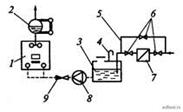
Figure 2. Scheme of forced condensate return: 1 - boiler; 2 - dry steamer; 3 - condensate tank; 4 - air tube; 5 - bypass line; 6 - steam valves; 7 - steam trap; 8 - make-up pump; 9 - check valve
The float steam trap (see Fig. 3, b) works like this. Steam and condensate through the inlet enter under the float 3, which is connected by a lever to the ball valve 4. The float 3 has the shape of a cap. Under steam pressure, it floats, closing the ball valve 4. The condensate fills the entire chamber of the steam trap; in this case, the steam under the valve condenses and the float sinks, opening the ball valve. The condensate is discharged in the direction indicated by the arrow until new portions of steam accumulated under the hood cause the hood to float. Then the steam trap cycle is repeated.
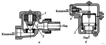
Figure 3. Steam traps: a - bellows; b - float; 1 - bellows; 2 - low-boiling liquid; 3 - float (overturned cap); four - ball valve
On the industrial enterprises having industrial consumers of high-pressure steam, steam heating systems are connected to heating mains according to high-pressure schemes (Fig. 4). Steam from a private or regional boiler house enters the distribution manifold 1, where its pressure is controlled by a pressure gauge 3. Then, through the steam pipelines 1 leaving the manifold, 2 steam is sent to industrial consumers, and through the T1 steam pipelines to the consumers of the steam heating system. Steam pipelines T1 are connected to comb 6 of steam heating, and comb 6 - to comb 1 through pressure reducing valve 4. Pressure reducing valve throttles steam to a pressure of not more than 0.3 MPa. The wiring of high-pressure steam pipelines of steam heating systems is usually carried out from above. The diameters of the steam pipelines and the heating surfaces of the heating devices of these systems are somewhat smaller than those of low-pressure steam heating systems.

Figure 4. Scheme of high pressure steam heating: 1 - distribution comb; 2 - steam pipeline; 3 - manometer; 4 - pressure reducing valve; 5 - bypass (bypass line); 6 - comb of the heating system; 7 - cargo safety valve; 8 - fixed support; 9 - compensators; 10 - steam valves; 11 - condensate pipeline; 12 - steam traps
The disadvantage of steam heating systems is the difficulty in regulating the heat output of heating devices, which ultimately leads to excessive fuel consumption during the heating season.
The diameters of the pipelines of steam heating systems are calculated separately for steam and condensate pipelines. The diameters of low-pressure steam pipelines are determined in the same way as in water heating systems. The pressure loss in the main circulation ring of the system? p pk, Pa, is the sum of the resistances (pressure losses) of all sections included in this ring:
where n is the fraction of pressure loss due to friction from the total losses in the ring; ?I is the total length of sections of the main circulation ring, m.
Then the required steam pressure in the boiler pk is determined, which should ensure that pressure losses in the main circulation ring are overcome. In low-pressure steam heating systems, the difference in steam pressure in the boiler and before heating appliances is spent only to overcome the resistance of the steam line, and the condensate returns by gravity. To overcome the resistance of heating devices, a pressure reserve p pr \u003d 2000 Pa is provided. The specific vapor pressure loss can be determined by the formula
| | (3) |
where 0.9 is the value of the coefficient that takes into account the pressure margin to overcome unaccounted resistances.
For low-pressure steam heating systems, the fraction of friction losses n is taken to be 0.65, and for high-pressure systems - 0.8. The value of the specific pressure loss calculated by formula (3) must be equal to or slightly greater than the value determined by formula (2).
The diameters of the steam pipelines are determined taking into account the calculated specific pressure losses and heat load of each calculated section.
Steam pipeline diameters can also be determined using special tables in reference books or a nomogram (Fig. 5) compiled for average low pressure steam densities. When designing steam heating systems, the steam velocity in steam pipelines should be taken taking into account the recommendations given in Table. one.
Otherwise, the methodology hydraulic calculation low pressure steam pipelines and circulation ring resistances is completely analogous to the calculation of pipelines leading CLASSIFICATION OF STEAM HEATING SYSTEMS
| Steam heating systems, as indicated in chapter I, are divided into vacuum-steam-absolute pressure<0,1 МПа (менее 1 кгс/см2), низкого давления - избыточное давление 0,005-0,07 МПа (0,05- 0,7 кгс/см2) и высокого давления - избыточное давление >0.07 MPa (more than 0.7 kgf/cm2). Low-pressure steam systems, in turn, are divided into open, communicating with the atmosphere, and closed, not communicating with the atmosphere. According to the method of returning condensate to the boiler, the systems are closed - with a direct return of condensate to the boiler and open - with the return of condensate to the condensate tank and its subsequent pumping from the tank to the boiler. According to the connection scheme of pipes with devices, systems can be two-pipe and one-pipe (both with upper, lower and middle piping, with dry and wet condensate pipelines), with associated steam and condensate flow and dead-end. Dry pipelines are called condensate pipelines, the sections of which are not completely filled with condensate, and during interruptions in the operation of the system are not filled with water. Wet pipelines are called condensate pipelines, which are always filled with water. |
heating systems
Steam heating. Principle of operation. Advantages and disadvantages. Steam as a heat transfer medium.
(kJ/kg)
where i n is the specific enthalpy of dry saturated steam, kJ/kg
i w - specific enthalpy of boiling water obtained by heating 1 kg of water from zero degrees to the boiling point.
r is the specific heat of vaporization obtained as a result of the conversion of 1 kg of water into steam at the boiling point.
Steam as a coolant:
The heat carrier is a liquid or gaseous medium moving in the heating system.
The heat carrier accumulates heat, and then transfers it to the heated room.
Advantages of application:
1) lower metal consumption for heating devices compared to a water system.
2) lower hydrostatic steam pressure in vertical pipelines.
3) low thermal inertia, which allows for rapid heating and rapid cooling.
4) the ability to move steam over long distances.
Steam Disadvantages:
1) heat steam, and hence the high surface temperature of the O.P., which leads to decomposition and dry sublimation of dust on the surface of the device, accompanied by the release of harmful substances. Oxides of CO in particular.
2) the impossibility of qualitative adjustment of the heat transfer of devices, because the temperature of the steam is constant.
4) accelerated corrosion of pipes.
Classification of steam heating systems. Features of steam heating.
1. Depending on steam pressure:
Subatmospheric (abs. pressure<0,10 мПа)
Vacuum steam (abs. pressure<0,11 мПа)
Low pressure (abs. pressure 0.105 - 0.17 MPa)
High pressure (abs. pressure 0.17 - 0.27 MPa)
2. According to the method of returning condensate to the boiler:
Closed (with direct return of condensate by gravity to the boiler)
Open circuit (with condensate return to the tank and its subsequent pumping to the boiler)
3. In connection with the atmosphere:
Open (i.e., the condensate tank communicates with the atmosphere)
Closed (non-communicating tank with the atmosphere)
4. According to the layout of pipelines:
Single pipe
Two-pipe
With top, bottom and middle wiring.
5. With pressure and gravity condensate drain:
Pressure - completely filled with condensate moved by the pump.
6. With dry and wet condensate drain. In dry air and condensate moves - gravity. Wet is completely filled with condensate - pressure.
The principle of operation is based on the transfer to the room of the latent heat of vaporization, which is released during the condensation of steam. Use dry saturated steam (i.e. in equilibrium with water).
Steam from the boilers enters the heating device through steam pipelines, where it condenses, giving off the latent heat of vaporization through the wall of the devices to the environment. Further, the condensate is discharged from the devices to the boiler room. When steam condenses, its temperature does not change, and the volume of steam decreases by an average of 1000 times.
A schematic diagram of low pressure steam heating is shown in the figure. It consists of three main elements: a steam boiler, heating devices, a network of pipelines.
The operation of the system is as follows. Water, which is filled with a heat generator - a boiler to a certain level, is heated. After heating the water above 100 ° C, steam is formed, which begins to mix through the pipelines to the heating device. Cooling in contact with the walls of the heating device, it condenses. In this case, mainly the latent heat of vaporization through the walls of the device is transferred to the heated room. The resulting condensate is returned from the device by gravity through pipelines (condensate lines) to the boiler for re-conversion into steam.

Since the heating device and pipelines are filled with air up to a piece of the system, steam can enter the device only after preliminary displacement of air, as a heavier medium.
Air is removed from the system, moving along the path of the steam to the heater and further along the condensate pipeline, moving in parallel with the condensate. Thus, the section of the condensate pipeline must be sufficient to move condensate and air.
The condensate pipeline, in which condensate and air move, is called conditionally dry. A dry condensate pipeline, laid with a slope i = 0.005 for gravity movement of condensate, passes into a vertical pipe, occupying the full cross section of which, the condensate returns to the boiler. At point a, connecting the horizontal pipe with the vertical one, the air is removed through the air pipe into the boiler room.
Thus, a steam heating system differs from a water heating system in that there is no expansion vessel in the steam system; air is removed from the system not through its upper point, but below (in the basement, in the boiler room), in front of the place where condensate enters the boiler, through a specially arranged air
The pipelines in the steam system are divided into steam pipelines leading to the heater, and condensate pipelines - from the heater to the heat generator.

Control over the supply of steam to the heating device can be carried out by installing a tee with a plug on the condensate line behind the device (see figure). By unscrewing the plug, it is possible to set such a mode by adjusting the valve on the steam supply pipe in which the steam will completely condense in the device. Steam that has entered the condensate pipeline will exit to the boiler room through an air pipe. Behind each heating device it is more expedient to install a vapor barrier that allows air and condensate to pass through, but prevents the passage of steam.
The principle of operation of the vaporizer is as follows. Hermetic corrugated box (bellows) filled with alcohol. At the temperature of the steam, the box expands, and the cone valve attached to it closes the hole for the passage of steam. When flushed with air or condensate, the temperature of which is lower than the steam temperature, the box does not stretch and the hole remains open.
The steam pressure in the heat generator is made up of pressure losses to overcome hydraulic resistance in the pipeline (ZiRl + Z) and in the heating device, in front of the valve of which a certain design pressure is provided.
Usually, the steam pressure in the heat generator is assigned depending on the length of the system - the distance from the heat generator to the most remote vertical riser. According to practice, with a system length of up to 100 m, pressure is taken up to 0.1 kg/cm2, up to 200 m - up to 0.2 kg/cm2, up to 300 m - up to 0.3 kg/cm2.
The value of the design steam pressure in the boiler is determined by the difference in water levels in the vertical section of the condensate pipeline (wet condensate pipeline) and in the heat generator.
A water column of height h must balance the steam pressure in the boiler. The height corresponds to the steam pressure in the boiler, expressed in meters of water column.
![]()
This diagram repeats, in essence, the completely considered schematic diagram of a steam heating system. This scheme differs in that here the steam from the heat generator (boiler) enters the main riser, then it is supplied to the heating devices through the main, vertical risers and upper connections. The condensate formed in the heaters flows down the condensate lines to the boiler.
The described scheme compares favorably with the others considered below in that steam enters the heating devices but risers from top to bottom, while the condensate formed in the risers-steam pipelines flows down the pipe walls in the same direction with the movement of steam. The only exception is the main riser, in which the condensate formed during the movement of steam (due to heat losses by pipelines) flows towards the steam. The associated movement of steam and condensate is expedient, since with such a movement of two media, the mode of movement of steam and condensate is not violated - there are no shocks, hydraulic shocks, which are characteristic of the countercurrent movement of steam and condensate in one pipe.
The supply line is laid with a slope towards the movement of steam, and the condensate line - with a slope towards the boiler.
Low pressure steam heating system with bottom wiring and gravity condensate return. Such a system differs from a system with an upper wiring in the position of the main steam pipeline and the device for removing (drying) condensate from the steam pipeline with a U-shaped loop.
The figure shows a hydraulic shutter-drainage valve. A tee with a plug is installed on the lower part of the loop, which is necessary for cleaning the loop, as well as draining water from it during a long shutdown of the system in order to prevent freezing of water in the loop.
The height of the U-shaped hydraulic seal is determined by the value H:
H \u003d H 1 + H zap,
H 1- the height of the water column, balancing the steam pressure at the point of connection of the hydraulic seal;
N zap, - margin, taking into account the vapor pressure in the pipeline, balancing the liquid column with a height of 0.2-0.25 m.
![]()

Compared to the above-described top-pipe system, the bottom-pipe system introduces steam to the heaters via risers, with the resulting condensate draining towards the steam flow. As a result, the speed of steam movement along the risers must be less than the speed of its movement in the risers of a system with an upper wiring. At high steam speeds, the latter, rising up, is able to pick up the condensate flowing down, which is accompanied by noise.
Low pressure steam heating system with medium distribution and dry condensate line. In buildings with a height of 3-5 floors, low-pressure steam heating systems with an average steam distribution are installed (Fig. V.5).
The steam line in such a system is laid under the ceiling of one of the floors; the part of the system above the steam line will be the same as the bottom piped system, and the part below the steam line will be the same as the top piped system.
The advantages of the system include rational (without special devices) condensate removal from the steam pipeline and rational placement of the main steam pipeline in a heated room. The heat transfer by the steam pipeline in this case is used for heating.
All condensate risers are connected to the overhead line, which is usually laid horizontally. To release air arrange a pipe a.
The main condensate pipeline, which in this system only serves to drain condensate, is completely filled with water, in contrast to a steam system with a dry condensate pipeline, and therefore it is called wet.

Low pressure steam heating system with condensate pumping to the boiler using a pump. Low-pressure steam heating systems with gravity condensate return can be arranged if the steam boiler is located below the heating devices.
In systems of great length, due to the increase in the design steam pressure in the boiler, it is necessary to deepen the boiler room accordingly.
If it is difficult to deepen the boiler room (usually at a pressure above 0.2 kg / cm2), a low-pressure steam heating system is used with condensate pumping using a pump. In this system, heaters can be installed below the boiler.
In a steam heating system with condensate pumping, the wiring of steam pipelines can be any - upper, lower, middle. Condensate from the heating system enters the condensate tank, from where it is pumped to the boiler with the help of a centrifugal feed pump (Fig. V.7).
The feed pump is recommended to be installed below the bottom of the condensate tank so that the pump is under the fill. The need for such a pump installation is explained by the fact that the suction height of the pump depends on the temperature of the pumped water: with an increase in the temperature of the hearth, this height decreases sharply. It should also be borne in mind that when a vacuum is created in the suction pipe of the pump, at which the boiling point of water decreases, hot water will go into a vapor state faster than cold water. The transition of water into a vapor state will drastically reduce (if not nullify) the performance of the pump. Installing a pump under the bay, that is, under the pressure of a water column, eliminates the possibility of the described phenomenon.
In a steam system with condensate pumping, air is removed through the condensate line and exits to the atmosphere through the condensate tank. A special air pipe is arranged in a closed tank for this purpose. To prevent steam from escaping into the atmosphere through the condensate line, a steam trap is installed at the end of this pipeline, v tank.
Steam heating systems equipment: steam traps, condensate tanks, safety devices.
1) steam traps- these are devices that prevent the penetration of steam into the condensate pipeline:
a) hydraulic valves

In them, during the operation of the system, the height difference of the columns h is maintained, balancing the steam pressure at the point of attachment of the loop to the steam line. Due to the difference, steam cannot penetrate into the condensate line. At the bottom of the loop is a tee for water release and cleaning.
b) inverted bucket steam traps:
principle of operation - the float floats under the action of steam and condensate from below. In this case, a ball valve connected to the float by a lever closes the outlet. The float filled with condensate drops and the outlet opens.
c) thermostatic steam trap:
1 - body, 2 - bellows (thermostat), 3 - cover, 4 - seat, 5 - spool
installed after heating appliances to retain uncondensed steam.
The bellows is partially filled with a liquid boiling at 90-95. When steam enters with the condensate, the liquid in the bellows boils. The bellows lengthens as a result of the increase in internal pressure and the spool closes the outlet in the seat. After filling the body with condensate and lowering its temperature by 8-20, the liquid vapor in the bellows condenses, the bellows shortens and the outlet opens.
d) thermodynamic:

1 - body, 3 - cover, 4 - seat, 6 - disc
Are established as float on highways at p>0,1MPa. When condensate enters from below, the disk rises above the seat and the condensate flows through the annular groove in the seat to the outlet.
2) condensate tank

To collect system condensate. The condensate must be filled<80% объема бака.
3) safety valve- prevent the increase in pressure in the system in excess of the calculated one.
There are: - springy; -lever
Characteristics of air heating. Comparative advantages and disadvantages. Classification of air heating systems. Amount and temperature of air for heating. Local air heating. Heating and heating-ventilation units. - 1 hour.
Air heating has much in common with other types of centralized heating. Both air and water heating are based on the principle of heat transfer to heated rooms by cooling the coolant. In the central air heating system, as well as in water and steam heating systems, there is a heat generator - a central installation for heating air and heat pipes - channels for moving the coolant - air.
The difference is that there are no heaters in the air heating system: hot air transfers the heat accumulated by it directly to the heated room, mixing with the internal air and moving along the surface of the fences. The range of air heating can be narrowed down to one room, heated by one or more water or steam air heaters. In this case, air heating becomes local and essentially turns into water or steam heating (however, the power of the air heater is much higher than the power of one conventional heater and intensive air circulation can be created in the room).
Air heating is also characterized by an increase in the sanitary and hygienic indicators of the indoor air. Air mobility favorable for the normal well-being of people, room temperature uniformity, as well as air change, purification and humidification can be ensured. In addition, when installing an air heating system, metal savings are achieved.
The possibility of combining air heating with forced ventilation in the cold period, with cooling of rooms in the summer brings air heating closer to ventilation and air conditioning and determines the scope of its application in industrial, civil and agricultural buildings.
The property of hot air - to quickly heat the room - is used in the implementation of periodic or standby heating.
Air heating is one of the most ancient methods of space heating. The use of heated air for heating buildings is known even before our era. The air heating system “hyupokaustum” (“warmed from below”) is described in detail by Vitruvius (end of the 1st century BC). Outside air was heated in underground channels, preheated by flue gases, and entered the heated rooms. According to the same principle, the premises of castles in Germany were heated in the Middle Ages, and the air was heated in fire-stone furnaces. In the "Russian system" of air heating, widespread in the middle of the 17th century, the possibility of combustion products entering the premises was excluded: the air was heated by contacting the outer surface of the Special Fire-Air Furnace. An example of such fire-air heating was the heating system of the Faceted Chamber in the Moscow Kremlin (end of the 15th century), where the air was heated in a central furnace in the basement.
The technique of fire-air heating was improved in the XVIII-XIX centuries. At the end of the XVIII century. architect N. A. Lvov published the rules for designing and calculating the system of fire-air heating. This system of heating the outside air in a fire-air heater and distributing it through channels into the premises was widespread in many European countries.
At the beginning of the XIX century. the German professor Meisner described the physical laws of air heating, the Russian engineer N. A. Ammosov used a “pneumatic furnace” - a fire heater with metal pipes for centralized air heating, replacing up to 30 room furnaces. "Ammos heating" has been used in capital civil buildings for many decades.
The lack of air heating with fire heaters - the possibility of fuel combustion products getting into the air - the coolant and with it into the heated rooms (there is even a known case of damage to paintings and wall paintings in the St. Petersburg Hermitage) - led to the replacement of fire heaters with water and steam. A modern metal heater is used in heating and ventilation systems of industrial, civil and agricultural buildings.
At the same time, air heating is not without significant drawbacks. As is known, the cross-sectional area and surface of air ducts, due to the low heat storage capacity of air, are many times greater than the cross section and surface of water ducts. In a network of considerable length, the air cools noticeably, despite the fact that the air ducts are covered with thermal insulation. For these reasons, the use of a central air heating system in comparison with other systems at a given cost may not be economically feasible. In an extensive network of a multi-storey building, it is also possible that the distribution of air in the premises during operation may be disturbed, which was shown by the experience of using air heating in residential buildings in the 60s. Local air heating does not have the listed disadvantages, however, it is not without negative features due to the placement of heating equipment directly in the room.
The need to remove heaters from the premises may prevent the use of local air heating. If, in addition, it is required to provide a number of premises with forced ventilation, then only with a central air heating system both these conditions are met together.
Classification of air heating systems.
Gravitational and fan air heating systems, as already mentioned, can be local and central
Schematic diagrams of the local air heating system. A pure heating system with complete recirculation of the coolant - air can be channelless and channel. With a ductless system, the air is heated in the heater and moved by the fan. The presence of channel 2 for hot air causes natural air circulation through the room and the heater. In the heat exchanger-heater, the primary heat carrier, cooling down, heats the air, i.e., overheats the secondary heat carrier in relation to the internal air of the room to perform the heating function. These two schemes are used for local air heating of rooms that do not need ventilation.
For local air heating of the room, two other schemes are used simultaneously with its ventilation.
According to the scheme with partial circulation part of the air is taken from outside; the other part of the air is mixed with the outside air (partial air recirculation is carried out). The mixed air is warmed up in the heater and supplied by the fan to the room. The room is heated by all the air entering it, and is ventilated only by that part of the air that is taken from outside. This part of the air is removed from the room into the atmosphere through the channel.
Straight-through scheme: outside air in the amount necessary for ventilation of the room is heated for heating and, after cooling in the room, is removed in the same amount into the atmosphere.
Central air heating system - channel. The air is heated to the required temperature in the thermal center of the building, where the primary coolant is supplied to the heat exchanger-heater.
In the scheme, the heated air is distributed through special channels throughout the premises, and the cooled air is returned through other channels for reheating in the heater. Complete recirculation of air is carried out without ventilation of the premises. The heat consumption in the heater corresponds to the heat loss of the premises, i.e. the scheme is purely heating.

An air curtain installation, often used at the external entrance to public and industrial buildings, can serve as an example of a local and central recirculation air heating system.
Recirculating air heating system has a lower initial investment and operating costs, but can be used in rooms where hygiene issues are not significant. The area of action of the central gravity air heating system is limited to approximately 10-15 m, counting along the horizontal path from the thermal center to the most remote vertical channel. This is explained by the small value of the effective natural circulation pressure, which, even with a significant temperature difference between hot and outdoor air [for example, 70 ° C - (-30 ° C) \u003d 100 °], is only about 4 Pa (0.4 kgf / m2) per every meter of channel height.
Air heating system with partial recirculation arranged with mechanical air movement propulsion and is the most flexible. It can operate in various modes: in the premises, in addition to partial, a complete change can be carried out, as well as complete air recirculation. With these three modes, the system operates as a heating-ventilation, pure ventilation and purely heating system. It all depends on whether and how much air is taken in from outside and to what temperature the air is heated in the heater.
Direct-flow air heating system has the highest operating costs, therefore it is used in those rooms where ventilation is required in a volume not less than the volume of air necessary to create the proper heating effect (for example, in rooms where substances harmful to human health are released, explosive, fire hazardous having an unpleasant odor). The movement of air with the help of a fan turns out to be necessary with a significant radius of the system, for heating rooms located below the thermal center, and for air purification in filters (also in the recirculation air heating system).
Amount and temperature of air for heating.
The air for heating the room is heated to such a temperature that, as a result of its mixing with the internal air and heat exchange with the surface of the fences, the set temperature of the room is maintained
The temperature of the hot air must be as high as possible in order to reduce, as can be seen from the equation, the amount of air supplied, and therefore the dimensions of the channels are reduced accordingly, as well as the power consumption in the fan system.
However, hygiene rules set a certain temperature limit - the air should not be heated above 70 ° C so that it does not lose its properties as an environment inhaled by people. This temperature is usually accepted for an air heating system for rooms with permanent or long-term (more than 2 hours) stay of people, if hot air is freely released into the upper zone (above 0.4 hp from the floor, where hp is the height of the room, m)
In a low room, a jet of hot air is laid on the ceiling. The temperature of the ceiling in the area of the jet, especially at the first meter from the grate, rises, and the temperature of the jet decreases. As a result, radiant heat transfer in the room is enhanced. In this case, the supply air temperature rise limit is set on the basis of the calculation of radiant-convective heat exchange with a check of the thermal comfort conditions in the room, similar to how it is done with panel radiant heating.
With free supply of hot air to the area of the room at a height of up to 0.4 hp from the floor, its temperature at a distance of more than 2 m from workplaces should not exceed 40-45 ° C. The exception is air-thermal curtains at external doors and gates, when a short-term exposure to a passing person, a higher temperature of the supplied air is allowed.
If a person is subjected to prolonged direct influence of a jet of heated air, it is recommended to lower the temperature of this air to 25 ° C.
The formula determines the mass amount of air supplied to the room only for the purpose of heating it, and the system is provided for recirculation. When the air heating system is also a ventilation system, the amount of air introduced is set under the following conditions.
If the mass amount of air for heating is equal to or exceeds the amount of air for ventilation, then the amount and temperature of the heating air are retained, and the system is selected as direct-flow or with partial recirculation.
If the mass amount of ventilation air exceeds the amount of air that is determined for heating purposes, then the amount of air for ventilation is taken, the system is provided for once-through, and the temperature of the supplied air is calculated by the formula
The amount of air for heating the room or its temperature is reduced if there are constant heat emissions in the room.
With a central heating and ventilation system, the temperature of hot air, determined by the formula, turns out to be different for each room. It is technically feasible to supply air with different temperatures to separate rooms, but this complicates the design and operation of the system and may turn out to be uneconomical.
It is easier, and sometimes more expedient, to supply air to all rooms with the same temperature. To do this, the air temperature is taken equal to the lowest calculated for individual rooms, and the mass amount of air supplied is recalculated according to the formula. Some increase in air exchange is useful from the point of view of hygiene.
Local air heating.
Local air heating is provided in industrial, civil and agricultural buildings in the following cases:
a) during working hours in the absence of a central supply ventilation system, and the heating system can be purely heating and combined with local supply ventilation;
b) during non-working hours in the absence and impossibility or economic inexpediency of using the existing supply ventilation system for heating.
For local air heating apply:
1) recirculation heating units with mechanical induction of air movement, forming a channelless air heating system
2) heating and ventilation units with partial air recirculation and direct-flow, also with mechanical induction of air movement
3) recirculating air heaters with natural air movement, forming a ducted air heating system
Heating and heating-ventilation units are intended only for heating or for heating combined with ventilation, workshops of industrial buildings, large premises of public and agricultural buildings, apartments of residential buildings.
Recirculating air heaters are used for heating individual rooms of buildings and stairwells of multi-storey buildings.
Air recirculation is allowed if the surface temperature of the heating elements meets the requirements of hygiene, fire and explosion safety of the premises.
A heating unit is a set of standard elements assembled together at the factory, having a certain air, thermal and electrical power. The units are manufactured for installation directly in heated rooms and are used for recirculation heating and hot air supply without any air ducts. Heating units are compact, powerful and relatively inexpensive equipment. Their disadvantages include the noise generated by the operation of the fan, which limits the scope of the units during working hours.
Heating units are divided into suspended and floor. Depending on the model, one suspension heating unit with an electric engine power of 4 to 2.8 kW can heat up to 20-103 m3 / h of air, transferring up to 1.25-106 kJ / h of heat to the room.
In floor heating units, not only axial, but also centrifugal fans are used, and their power can exceed the power of suspended units. The air is heated not only by steam and water, but also by burning gaseous fuels.
For space heating, it is rarely possible to choose one unit that exactly meets the needs, and in most cases it is necessary to install several heating units in one room.
It is economically more profitable to use enlarged heating units. Studies have found that when using large heating units, the air temperature in the room remains fairly uniform - it differs from the calculated one by no more than 2-3 °, which is acceptable in many industrial buildings. Heated air is released from the units in concentrated jets at a significant speed of 6-12 m/s. This method of heating is called air heating with concentrated air supply.
When air flows through the control grille of the unit, a so-called compact jet is formed. The air jet turns into an incomplete fan jet when the regulating grid is supplemented with a scattering one.
The concentrated supply of heated air is carried out horizontally at the level (0.35-0.65) hp from the floor (hp - the height of the room). The rate of air release from the control grille of the unit is associated with the allowable air mobility in the working area of the room.
During the research, it was found that with an increase in the air exchange rate from 1 to 3, the air temperature along the height of the room becomes more uniform, while a further increase in the air exchange rate practically does not affect the air temperature in the upper zone. It has also been established that, subject to the conditions described above in relation to the speed, height of the outlet and the frequency of air exchange, the concentrated supply of heated air causes a change in its temperature by only 0.1-0.15 ° per 1 m of height, and the air temperature in the upper zone of high workshops differs from the temperature in the working area by no more than 3 °.
The most advantageous rate of air exchange in the room according to the lowest power consumption in heating units is found with a compact air jet according to the formula
If the air exchange rate is selected by the formula, then the temperature of the hot air supplied by the heating units is calculated by the converted formula
The heating and ventilation unit is similar in design to the heating unit, with the exception of the air intake part. Heating and ventilation units in industrial, public, auxiliary and agricultural buildings are used for concentrated supply of heated air. The number of these units is selected in the same way as the number of heating units. The air exchange in the room is determined by the formula and compared with the volume of ventilation air, since it must meet the requirements of ventilation of the room. The final supply air temperature is calculated from the formula.
The heating and ventilation unit in residential buildings is used for air heating of individual apartments, in particular those built from three-dimensional elements (block apartments). In addition to the unit located in the filing under the ceiling of the corridor of the apartment, they also lay an outdoor air duct with an air intake grill, a recirculation duct and supply air ducts with a control grill in each living room. Apartment air heating refers to duct fan systems of local air heating.
Heating systems are divided into local and central. Local systems include systems in which the heat generator and the heating device are located directly in the heated room (stove heating, heating with gas and electric appliances). Central heating systems called systems in which heat generators are located outside the heated room. The coolant, heated in the generator, is supplied through heat pipes to separate rooms and, having transferred heat to the air through heating devices, returns to the heating point.
Central systems by type of coolant can be water, steam and air.
Water systems heating can be with a water heater up to 100 ° C and above (overheated). Currently, the maximum value of water temperature is assumed to be 150°C. The main advantages of water heating systems are the ability to maintain a moderate temperature on the surface of heating devices, which prevents dust from burning on them; in the simplicity of the central regulation of heat transfer of heating devices by changing the temperature of the water; in ease of maintenance. The disadvantages of this system include: high hydrostatic pressure in the lower part of the systems, which limits the height of the systems; danger of freezing of water in a pipeline laid in an unheated room.
According to the method of water circulation, central water heating systems are divided into systems with natural circulation (due to the difference in densities of cooled and hot water) and systems with mechanical stimulation (artificial), in which water is moved by a pump.
According to the scheme of laying conductive pipelines, water heating systems are divided into two-pipe and one-pipe. AT two-pipe systems water enters the heating devices through one risers, and is discharged through others (the devices are connected in parallel). AT single pipe systems water enters the device and is discharged from it in one riser (the devices are connected in series).
According to the location of the supply lines, water heating systems are divided into overhead systems (when laying supply lines in the attic or under the ceiling of the upper floor) and systems with bottom wiring (when laying supply lines in the basement, above the floor of the first floor or in underground channels). In the direction of water movement in the supply and return lines, water heating systems are dead ends (with oncoming water movement) and with passing traffic (when water moves in one direction).
Consider a schematic diagram of water heating. Its main parts are a heat generator (boiler), an expansion vessel, heating devices, a supply (hot) pipeline and a return (cold) pipeline. The system works as follows. After filling the system with water from the water supply and removing air from it, they begin to heat the water in the boiler. The heated water rises through the pipeline, then falls down and flows under the influence of natural pressure with the continuity of the flow to the heating devices, to which it gives off part of its heat. The water cooled at the outlet of the device flows through a closed circulation circuit to the heat source (boiler), while displacing lighter heated water from it. Water, having replenished heat losses in the boiler, repeats its movement (circulates).
To speed up the circulation of heated water in the system, pumps can be used that are installed in front of the boiler. Such systems are called pumping systems.
The water heating system is a closed circuit filled with water. Therefore, even a slight increase in its volume with an increase in temperature can create a pressure that exceeds the ultimate strength of individual elements of the system, and a decrease in volume with a decrease in temperature causes a break in the jet and disruption of circulation. To avoid these phenomena, a device must be provided in the heating system that perceives excess water when the temperature in the system rises and replenishes the loss of water when it decreases. The most simple and trouble-free device of this kind is an expansion tank. The expansion tank is a container connected to the heating system and communicating with the atmosphere. It is installed above the highest point of the system.
Steam systems Heating systems differ from water heating systems in that the source of heat supply is saturated steam, which is supplied from the boiler through steam pipelines to heating devices, where it gives off part of the heat and turns into condensate. Condensate is discharged from the devices through pipelines to collection condensate tanks, from where it is pumped to the boilers by pumps. In some cases, the condensate is returned by gravity directly to the boilers.
The pipelines in the steam system are divided into steam pipelines leading to the heater, and condensate pipelines carrying condensate from the heater to the heat generator. The condensate pipeline, the cross section of which is not completely filled with condensate during system operation, and is free of water during interruptions in the system operation, is called dry. Wet is a condensate pipeline that is always completely filled with water. The condensate pipeline can be pressurized if the condensate is moved using pumps or excess steam pressure, and independent if the condensate is moved by gravity.
In steam heating systems, steam moves due to the pressure difference at the outlet of the boiler and in front of the heating devices.
The advantages of steam heating systems are higher heat transfer of heating devices; in less than that of water heating systems, metal consumption for pipes and heating devices; less danger of freezing; in the possibility of moving steam over long distances without the use of artificial stimulation.
Water heating
Water heating currently the most common type of central heating. This is mainly due to the fact that in a water heating system, by changing the water temperature, it is easy to control the heat transfer, which must be changed all the time depending on the change in the outside temperature, which affects the heat loss of the heated premises. This feature of the water heating system, which is also possessed by air heating systems, is called quality regulation .
To ensure high-quality regulation in a boiler house or at a CHP, water is heated according to a temperature schedule, according to which, in accordance with the outside temperature, the temperature of the coolant is set. At the same time, the higher the outside temperature, the lower the temperature of the heat carrier (water) should be. At very low outside temperatures, the opposite is true.
According to the method of induction, water heating is divided into systems with pumping and natural induction. More common pumping systems, in which water circulates mainly under the action of a circulation pump. The latter is installed on the return line, through which water flows, cooled in the heating system in front of the water heater (boiler or boiler). It should be borne in mind that conventional circulation pumps during operation create noise that can spread to neighboring rooms.
In cases where heating systems are connected to central heating and network water flows directly into these systems, the latter do not have their own circulation pumps, since water circulates in them under the action of pumps installed at CHP stations or central boiler houses.
The locations of the distributing pipelines in water heating systems and the methods of connecting heaters may be different. More common are single-pipe circuits, one of the varieties of which (with top wiring) is shown in Figure 6.1. The diagram shown in this figure, like all the previous ones, is of a fundamental nature: it shows a limited number of heaters and risers, all of which are located in the same plane.
Upon completion of the installation of the system, it is first of all checked for tightness by a hydraulic test, for which the system is temporarily disconnected from the expansion vessel designed to distribute pressure, and using a hydraulic press, pressurization is carried out at increased (against operating conditions) pressure.
After the detected installation defects are eliminated, an expansion vessel is attached to the system and it is filled with water from the water supply line to the lowest water level in the expansion vessel. It is installed at the highest point of the heating system: usually in the attic or in the superstructure (often above the stairwell). Connect the expansion vessel to the pump heating system with an expansion line in front of the pump
Hot water during system operation flows from the boiler or boiler to the main riser, from it to the hot distribution main and from there to the system risers. From the risers, water enters the heating appliances, gives off its heat to them, and then returns to the boiler or boiler through the return line, from there it again enters the main riser, etc.
Hot water during system operation flows from the boiler or boiler to the main riser, from it to the hot distribution main and from there to the system risers. From the risers, water enters the heating appliances, gives off its heat to them and then returns to the boiler or boiler through the return line, from there it again enters the main riser, etc.
To bring the heating system into action, the boiler and the circulation pump are turned on. As you know, water expands when heated.
To accommodate this additional volume of water, an expansion vessel is used, the capacity of which is between the lower and higher levels. The levels are marked by connecting to the signal and overflow lines: the lower signal line is led to the boiler room or boiler room, the upper overflow line to the sewer. Disadvantages of the steam heating system: high temperature on the surface of pipes and heating devices, causing dust to burn and creating unsanitary conditions in the room; the impossibility of flexible central regulation of heat transfer of heating devices, in connection with which regulation is applied by passes (by periodically turning the system on and off); more complex operation and higher useless heat losses from pipelines laid in unheated premises.
Steam heating
Steam heating systems, depending on the steam pressure, are divided into low pressure systems (with pressure from 0 to 70 kPa), high pressure (from 70 to 600 kPa) and vacuum steam systems, when the pressure is less than atmospheric pressure. The latter, due to the complexity of operation and the lack of advantages compared to water heating systems, are now almost never used. Steam pressure is measured on a boiler located in a heated building or at a heat input to a building.
More often than not, low-pressure steam systems are more common among the systems listed above: they are more convenient and safer to operate than high-pressure systems, and can be serviced by a boiler located in the lower floor or basement of a heated building.
Several low-pressure steam heating schemes have been created. They are distinguished by the location of the distributing steam pipelines, the connection of heating devices and the method of condensate removal.
More often, a scheme with an upper wiring and a “dry” condensate line is used (Figure 6.2). Steam from the boiler under excess pressure enters the main riser, from it to the distributing steam pipeline located on top of the heating devices, and then to the riser. Further, the steam goes through the steam lines to the heating devices, where, upon contact with the inner surface of the walls, it cools, giving up its latent heat of vaporization, and condenses. The condensate flows back to the boiler through the condensate line, where it is again converted into steam; From the boiler, the steam again enters the heating appliances. The amount of steam that enters each heater, according to the design conditions, must correspond to its heat transfer. Before starting steam into the system, it is filled with air heavier than steam, which, when the system is filled, is displaced by steam and exits through the air vent. When the system stops, i.e., the supply of steam and its condensation are stopped, air, on the contrary, enters the system through the air vent and fills the resulting vacuum. At the same time, air enters and leaves the system through the condensation line, and therefore it must have an increased diameter.
The movement of condensate along the line occurs due to its slope, taken at least 0.003. With a slope (in the direction of steam movement), a distributing steam pipeline is also laid. This is done to ensure the descent through the devices into the condensate line of the associated condensate, which is obtained due to the cooling of the steam pipeline and partial condensation of the steam.
Figure 6.2 - Schematic diagram of low-pressure steam heating with upper wiring, dry condensate pipeline and gravity return of condensate to the boiler:
1 - steam boiler; 2 - main riser; 3 - distributing steam pipeline; 4 - risers; 5 - steam connections; 6 - heating devices; 7 - condensation line; 8 - control valves; 9 - air outlet.
Steam heating systems use the property of steam during condensation to release the latent heat of phase transformation. When condensing 1 kg of steam in a heating device, the room receives about 2260 kJ of heat.
Compared to hot water heating systems, steam heating systems have the following advantages:
1) due to the low density of steam, it moves with large
speeds, as a result of which smaller diameters of heat pipes are required than with water heating, therefore the cost of heat pipes in steam heating systems is lower than in water heating systems;
2) a higher heat transfer coefficient from steam to the walls of the heater (due to the high latent heat of phase transformation), due to this and the high temperature of the steam, the surface area of heaters in steam heating systems is approximately 25-30% less than in water heating systems;
3) rapid heating of the premises and shutdown of the system from work;
4) the possibility of using heating systems in high-rise buildings due to low steam density.
However, along with all the listed positive properties, steam has a number of significant disadvantages:
1) the impossibility of central quality regulation (changes in the temperature of the coolant) of the heat supply, as a result of which it is difficult to maintain a constant and uniform temperature in the room; ensuring a constant temperature is achieved by periodically turning off the system (regulation by "passes"), which is inconvenient in operation;
2) air pollution by products of dry sublimation (decomposition) of organic dust deposited on the surface of heating appliances;
3) large heat losses of steam pipelines;
4) reduction in the service life of steam pipelines as a result of air entering the system during its periodic shutdown, which causes corrosion intensification, especially of condensate pipelines.
The disadvantages of steam as a heat carrier do not allow using it for heating residential buildings, hostels, children's and medical institutions, libraries, museums and a number of others.
In accordance with SNiP 2.04.05-86, it is recommended to install steam heating systems in industrial premises (according to mandatory appendix 10), as well as in stairwells, pedestrian crossings, lobbies and heating points.
Classification, diagrams and equipment of steam heating systems
Steam heating systems are divided into:
Due to the presence of connection with the atmosphere,
According to the value of the initial steam pressure,
The method of returning condensate to the boiler or to the heating network,
The location of the steam pipeline and the layout of the risers.
Currently, open (communicating with the atmosphere) heating systems are used.
According to the pressure supplied to the heating system, heating systems are distinguished:
High (pex >0.07 MPa),
Low (r izb<0,07 МПа) давления;
Vacuum steam (r abs<0,1 МПа).
Vacuum steam systems are not used in our country.
According to the method of condensate return, steam heating systems are divided into:
Closed (due to the slope of the pipelines, condensate returns by gravity from the heaters to the boiler or to the heating network);
Open (condensate first enters the condenser tank, and then pumped to the boiler or to the heating network).
According to the location of the steam pipeline and the scheme of risers, steam heating systems can be performed in the same way as water heating systems, i.e. with upper, lower and intermediate steam distribution with one-pipe and two-pipe heating service schemes.
On fig. 9.1 shows a diagram of a closed low pressure steam heating system with overhead steam distribution. Steam from the boiler through the main riser 1, due to the pressure difference in the boiler and in the heating devices, it rises into the main steam pipeline 2 and further along the steam risers 3 and branches 4, equipped with valves, reaches the heating appliances. Here, the steam condenses, releasing the latent heat of vaporization into the heated room through the walls of the appliances. The resulting condensate through the condensate risers 5 and the collection condensate pipeline b, laid with a slope (not less than 0.005) in the direction of its movement, returns by gravity to the boiler, which is significantly lower than the heaters, so that the condensate column h balances the steam pressure in the boiler. For example, at a steam pressure in the boiler pg = 0.02 MPa, the condensate column h must be at least 2 m.
For normal removal of air from the system, the diameter of the condensate pipeline in the scheme under consideration must be such that the flowing condensate fills no more than half the diameter of the pipe. Compliance with this condition allows the air space of the condensate pipeline to communicate with the atmosphere using pipe 7 9. The place of connection of pipe 7 to the condensate pipeline must be above the water level //-// (see Fig. 9.1) by at least 250 mm; stop valves are not installed on it. Under this condition, the main condensate pipeline will never be completely filled with water. Such systems are called steam heating systems with a "dry" condensate line.
With a large length of the steam pipeline in closed systems, to reduce the depth of the boiler rooms, the condensate pipeline is laid below the water level in the boiler. Such a condensate pipeline is called “wet”, since it is completely filled with condensate. Air is removed from the heating system with a “wet” condensate line through a special air network of pipes with a diameter of 15-20 mm, connected to condensate risers 250 mm above the possible level of condensate in them.

Fig.9.1. Scheme of steam heating with upper steam distribution.
Fig.9.2. Steam heating system with bottom steam distribution.
A low-pressure steam heating system with lower steam distribution differs from a system with upper distribution mainly in the location of the main steam pipeline, in which a special hydraulic seal is installed or a water trap is installed at the far riser to drain condensate from the risers and the main steam pipeline (Fig. 9.2).
Open-loop steam heating systems (Fig. 9.3) are used at a steam pressure of Rg = 30 kPa and above. In contrast to a closed system, the condensate in it does not flow into the boiler 1, but into the condensate tank 3, from where the pump 2, switched on automatically or manually, is fed into the boiler. In these steam heating systems, the heaters can be positioned at any height relative to the boiler.
A horizontal single-pipe flow system is used, which is economical and quite acceptable for heating large premises of buildings of 1-2 floors, in which individual adjustment of the heat transfer of devices is not required. High-pressure steam heating Р abs > 0.17 MPa is usually taken in cases where steam is generated in factory boilers and its main consumer is production.
Consider the control unit and the scheme of high-pressure steam heating with upper steam distribution (Fig. 9.4). Steam from the boiler room enters the control unit with a pressure of Psb=0.6 MPa, which is necessary for production. A steam distribution manifold is installed for steam distribution 2 with two branches.
Since for the heating system of a building, steam can be used with pressure R izb not higher than 0.3 MPa, then to reduce the pressure from 0.6 to 0.3 MPa, a pressure reducing valve is installed in front of the second steam distribution manifold 3 bypass line 4 (in case of repair). After the pressure reducing valve, a safety valve of lever type 5 is installed, adjusted to p;! 3 b \u003d 0.3 MPa. Pressure gauges are available to monitor the pressure on the tori 1. From the second steam distribution manifold, steam enters through the main risers and steam pipelines 6 and heating risers 7 into heating devices. Valves 9 are installed at the devices on the steam and condensate lines; they are necessary in order to reduce the passage of steam into the condensate line and turn off the devices. In a high-pressure steam heating system, significant thermal elongations of pipelines occur (up to 1.5-2 mm per 1 m). To compensate for elongations, pipeline turns are used and compensators are installed on straight main pipelines. 8.
High-pressure steam heating systems are used only open-circuited. To prevent the breakthrough of steam from heating appliances, steam traps are installed in the condensate pipeline and the condensate tank. 10 or retaining washers that allow condensate to pass through and retain steam.

![]() Fig.9.3. Scheme of a horizontal single-pipe flow open low-pressure steam heating system with condensate pumping.
Fig.9.3. Scheme of a horizontal single-pipe flow open low-pressure steam heating system with condensate pumping.
1 - boiler, 2 - condensate pump, 3 - condensate tank
Fig.9.4 Scheme of high pressure steam heating system with upper steam distribution.