Big encyclopedia of oil and gas. Automation of steam and hot water boilers: control system "Contour
Introduction
Improving technology and increasing labor productivity are among the most important tasks of the technological process. An effective solution to these problems is possible with the introduction of automatic control and regulation systems for both individual objects and processes, and production as a whole.
Automation is a qualitatively new stage in the improvement of production. The main duties of a person in this case are monitoring the parameters of the process of performing freelance operations. The use of automation tools allows you to increase the number of units and mechanisms serviced by one person. The main operations that a person performs in this process are turning the units on and off, and in case of emergency situations, turning off the regulator and taking over the control functions. To do this, he uses the means of remote control of mechanized drives of various regulatory bodies. The use of technological protection means, blocking and automatic switching on of backup mechanisms makes it possible to automate the process of eliminating emergency situations.
A modern automatic system should perform two tasks:
1) to ensure the required accuracy of changing the output value of the system in accordance with the input value coming from outside, which plays the role of the program. In this case, it is necessary to overcome the inertia of the control object and other elements of the system, as well as to compensate for the distortion resulting from inaccurate knowledge of the characteristics of individual elements and the instability of their parameters. This is sometimes referred to as management in the narrow sense or tracking;
2) for a given value of the input quantity, the system should, if possible, neutralize the effect of external perturbations that tend to deviate the output value of the system from the value assigned to it at the given moment. In this sense, one speaks of the problem of regulation or stabilization.
AT given time With the development of the computer industry, control over technical processes in production has been greatly facilitated. Development computer science led to the creation of large automatic systems for managing complex production processes and entire industries.
1. Technological process
In modern industry building materials in the production of asbestos-cement products, air-hardening conveyors are widely used.
In air hardening conveyors, asbestos-cement pipes come from a pipe-forming machine.
The conveyor for air hardening of asbestos-cement pipes is a chain roller conveyor with 3 tiers, the canvas of which is a support for the pipes. The conveyor is mounted in a gallery lined with heat-insulating material.
Saturated steam from the steam boiler enters the gallery through the pipeline through the pipeline to humidify the air, create an environment with a temperature of plus 30 0 C and a pressure of 0.5 MPa. The pre-hardening process in the conveyor is combined with the operation of maintaining the cylindrical shape of the pipe. The rollers of the conveyor are an endless chain that moves along a metal or wooden deck, along the conveyor, rotating around its own axis.
A molded asbestos-cement pipe from a pipe-forming machine is placed on the rollers, which is driven or rotated and moves along the upper tier of the conveyor. Having reached the end, the pipe is laid along the guide plate on the rollers of the second tier of the conveyor moving in the opposite direction, it then also falls on the rollers of the third tier.
During the passage of the conveyor, the pipes gain strength sufficient for further transportation. Finished pipes are subjected to various tests.
The main test is to determine the test hydraulic pressure, while the pipes should not show signs of water permeability.
The compressive strength of samples cut from high density asbestos-cement pipes and aged for more than three months is from 300 to 700 kg/cm 3 , depending on the application of the load. The specific gravity of asbestos-cement products is about 2.75 kg/m 3 . Their volumetric weight is from 1600 to 2200 kg/m 3 . Asbestos-cement pipes are fire-resistant, have low thermal and energy conductivity, significant resistance to atmospheric pressure.
2. Choice of parameters
To improve the quality of output asbestos pipes it is necessary to maintain stable technological parameters, for this purpose they are monitored and regulated.
Controlled parameters may deviate from the norm, which leads to the rejection of products.
Automation systems are designed to maintain a certain temperature in the conveyor. Due to this, the asbestos pipes are hardened in the air hardening conveyor. In the event of a deviation from the set temperature, product defects may occur.
The automatic pressure control system is designed to maintain steam pressure in the control system. Due to this, the evaporation of moisture from the product is ensured in the air hardening conveyor. This drying system eliminates the formation of cracks on products and their deformation.
The control drying mode is changed by the amount of steam supply.
The following parameters are controlled in the pipeline:
- steam pressure,
- steam consumption,
– air humidity,
is the steam temperature.
The quality of products depends on the humidity, temperature and pressure.
Technological parameters to be controlled and regulated are summarized in Table 1.
Table 1
Name measurable quantities |
Value parameter |
converter |
Place of selection |
impact |
| Steam pressure regulation, Pa | 500 | steam line | water vapor | |
| Steam pressure control, Pa | 500 | Strain gauge transducer Metran - 100Di |
steam line | water vapor |
| Steam flow control, m 3 /h | 15 | Diaphragm pressure gauge |
Steam line input | water vapor |
| Temperature control in the hardening chamber, ˚С | 50 | Curing chamber | water vapor | |
| Control of air humidity in the curing chamber, % | 80 | Resistance thermometer platinum. |
Curing chamber | Gas medium |
| Temperature control in the hardening pool, ˚С | 60 | Copper resistance thermometer. |
hardening pool | Gas medium |
3. Selection of primary devices and secondary devices
For high-quality operation of the hardening conveyor, it is necessary to most accurately control and regulate technological parameters.
To do this, you need to choose the optimal primary and secondary devices.
3.1 Regulation and control of steam pressure
To measure steam pressure in a steam line, a Metran-100 strain gauge pressure transducer is used, which is designed to convert steam pressure into a unified current signal. The sensor consists of a strain gauge and an electronic unit. The sensitive element of the strain gauge is a single-crystal sapphire plate with silicon film strain gauges, firmly connected to the metal membrane of the strain gauge. The transducer electronics converts this change in resistance into a unified current output signal.
Specifications Metran-100DI converter are summarized in Table 2.
table 2
To work in conjunction with the primary device, a secondary device is used - KSU2.
KSU2 - self-recording compensator with a unified signal, small-sized version with a strip diagram. KSU2 is designed to measure and record pressure. Structurally, the device is made of separate modules and blocks (module measuring system, power supply, amplifying), interconnected by wires through plug-in connectors.
The technical parameters of the KSU2 device are summarized in Table 3.
Table 3
3.2 Monitoring the steam flow at the inlet of the steam line
To measure the steam flow rate, a restrictive device (CS) is used to create a pressure drop. The principle of action is based on the change in energy during the passage of matter through the SU.
Before and after the SS, holes are made in the pipeline and connected with impulse tubes to a differential pressure gauge that measures the pressure drop ΔР, Pa, on the SS according to the dependence
Impulse tubes are designed for pressure drop P 1 and P 2 to differential pressure gauge. Impulse tubes are seamless steel tubes.
Technical characteristics of impulse pipes are summarized in table 5
Table 5
Condensation vessels are included in the differential pressure gauge when measuring steam flow. Impulse tubes are designed to maintain a constant level of the vapor condenser above the level of the liquid filling the differential pressure gauge. In this project, condensation vessels model 5560 are used, made of structural quality steel - steel 20 GOST 1050–2005.
The differential pressure gauge is designed for remote differential pressure. The sensing element is a membrane block of two boxes welded from two membranes whose profiles match. Membrane boxes are separated by a cushion forming two chambers - lower and upper.
The internal cavities of the boxes are interconnected and filled with distilled water. The core of the differential transformer is connected to the center of the upper membrane. Under the action of pressure in the upper and lower chambers, the lower box is compressed, the liquid from it flows into the upper one, which leads to the movement of the core and a change in voltage and phase at the output of the primary device.
Technical characteristics of the membrane differential pressure gauge-flowmeter DM-3574 are presented in Table 6.
To work in conjunction with the primary device, a secondary device is used - KSD2.
KSD2 - self-recording compensator with a differential - transformer circuit, miniature version with a tape ideogram. KSD is designed to measure and record pressure. Structurally, the device is made of separate modules and blocks (measuring system module, flow module, power supply, amplifying and actuator), interconnected by wires through plug connectors.
The technical characteristics of the KSD2 compensator are summarized in Table 7
Table 7
3.3 Temperature control in curing chamber and pool
As a primary transducer for measuring temperature, TCM is used - a copper resistance thermometer.
The principle of operation of a resistance thermometer is based on the property of metal conductors to change their electrical resistance with a change in temperature. With an increase in temperature, the resistance of the metal conductor R t, Ohm, increases according to the following dependence
To work in conjunction with the primary device, a secondary device is used - KSM2.
KSM2 - self-recording compensator with a bridge circuit, miniature version with a tape ideogram. KSM is designed to measure and record pressure. Structurally, the device is made of separate modules and blocks (measuring system module, flow module, power supply, amplifying and actuator), interconnected by wires through plug connectors.
The technical parameters of the KCM2 compensator are given in Table 9.
Table 9
3.4 Humidity control in the curing chamber
To determine the humidity of the air in the hardening chamber, psychrometers are used.
Structurally, it consists of two platinum "dry" thermometers that measure the temperature of the air, the humidity of which is determined. The other "wet" thermometer is continuously humidified. Between these thermometers there is a psychrometric difference in their readings. The measuring circuit of the psychrometer consists of two bridges with two common arms. "Dry" TSP in one shoulder of the bridge, "wet" in the other. The voltage on the diagonal A - B of the bridge, proportional to the temperature of the "dry" resistance thermal converter, is in antiphase with the voltage taken from the diagonal A - C of the bridge, proportional to the temperature of the "wet" resistance thermal converter.
Technical characteristics of the TCM2 device are given in Table 10
Table 10
To work in conjunction with the primary device, a secondary device is used - KSM2 technical characteristics are given in table 9.
4. Properties of the control object
To stabilize the pressure in the course project used primary transducer pressure sensor Metran-100Di, which transmits a signal to the control device. The electrical signal transmitted to the control device is the signal of the control law, which is formed by the control device.
To determine the signal of the control law, the dynamic parameters of the control object are determined. The dynamic parameters are:
1) Delay,
;2) time constant,
;3) transfer coefficient of the control object,
.The air hardening conveyor is a multi-capacity control object. To determine the dynamic parameters, an acceleration curve is built, shown in Figure 2.
|
where ΔP is the pressure difference, kPa;
Δμ is the difference in the position of the regulatory body, %.
According to technological requirements, the pressure regulation time
, sec, in the air hardening conveyor should not exceed 30 sec.The control time for the selected proportional integral differential control law is determined from the graphical dependencies
|
Based on the calculations, a proportional integral differential control law is applied. The quality of control according to the chosen control law depends on the tuning parameters.
The purpose of adjusting the control device is to provide the most favorable transient process, i.e. the duration of the transient process is minimal, and the fluctuations of the pressure deviation decay quite intensively.
The tuning parameters proportionally to the integral differential control law are:
– K p - transmission coefficient of the control device;
– Т – integration time constant;
– Td – time constant of differentiation.
The estimated control time does not exceed the required time of 30 sec, therefore, for this control object, a proportionally integral differential control law is applied, which has R d = 0.56 and t p = 0.4 sec, since it provides the optimal time.
The coefficient of proportionality of the regulating device K p
calculated by the formula:
|
K p is checked by graphic dependencies.
|
where K c is the coefficient of the system.
The calculation of tuning parameters using approximate formulas and graphical dependencies are approximately the same.
5. Choice of control device
In accordance with the chosen control law and on the basis of mathematical calculations, we choose RM Remikont R-130.
Remikont R-130 is a compact low-channel microprocessor controller designed for automatic regulation and logical control of technological processes.
Regulatory model P-130 allows for local, cascade, program, multi-connected regulation. Moreover, all these operations are performed without impact. P-130 allows you to convert signals and generate pulse and discrete control commands.
Regulating model P-130 contains means of operational control of the location on the front panel of the controller. These tools allow you to manually change the mode of operation, set the task, control the course of the program, manually control the actuators, monitor signals and induce errors.
The controller is designed to receive and output analog and discrete signals. The formation of pulse signals at the output of the pulse controller is used by software, and all these signals are fed to the actuator through the discrete outputs of the controller.
The composition of the R-130 recomponent is described below.
Regulatory model R-130 provides:
1) up to four independent control loops, each of which can be local or cascade, with analog or pulse input, with manual or program setpoint;
2) a variety of custom-made combinations of analog and discrete inputs and outputs;
3) 76 "protective" in ROM algorithms for continuous and discrete processing of information;
4) up to 99 algometric blocks with free filling with any algorithms from the library with free configuration between themselves and the transformation inputs, the execution of mathematical functions and the development of logical control actions.
Installation of the device Remikont-130 is carried out on the setting console. The Setting Tool is the service operator's tool. With it, you can program the controller, configure its parameters, and also control signals at the internal points of the virtual structure.
The automatic control system must ensure reliability and stability.
Using the equation, the stability of the control system is checked using the Hurwitz and Mikhailov criteria.
5.1 Hurwitz stability criteria
The automatic control system is described by the equation
|
11p3 +55p2 -10p+35=0,
The equation is solved using a matrix.
a 1 a 3 0 a 1 = 11; a 2 = 55; a 3 = 10
0 a 2 0Δ1 = a 1 = 11 > 0
0 a 1 a 3 Δ2 \u003d a 1 ∙ a 2 - 0 ∙ a 3 \u003d 11 * 55 - 0 * 10 \u003d 605 > 0
Δ3 = a 1∙∙a 2∙a 3 + 0∙a 1∙0 + 0∙0∙a 3 – 0∙a 2∙0 – 0∙a 1∙a 1 - a 3∙0∙a 3 =
11*55*10+0*11*0+0*0*10–0*55*0–0*11*11–10*0*10=6050>0
According to the conditions of the Hurwitz criterion, the system is stable.
5.2 Mikhailov stability criteria
The equation also defines the Mikhailov stability criteria
11p3 +55p2 -10p+35=0
11jw 3 +55p2–10p+35=0
11jw 3 -55w 2 -10p+35=0
The original equation is divided into two equalities real and imaginary.
U(ω) = -55jω 2 + 35 = 0
V(ω) = -11jw 3 -10jw = 0
The calculation results are summarized in Table 11.
The hodograph is shown in Figure 3.
Table 11
| ω | 0 | 0,25 | 0,5 | 0,75 | 1 | 1,25 | 1,5 |
| U(ω) | 35 | 31,5 | 21,25 | -6,25 | -20 | -20 | -51 |
| V(ω) | 0 | -5,25 | -10,5 | -15,75 | -21 | -26,25 | -31,5 |
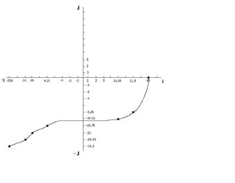
Figure 3 - Hodograph
Since the hodograph passes through three quadrants, which corresponds to the degree of the equation, the system is stable.
6. Choice of automation tools
6.1 Circuit breaker
The circuit breaker is used as protection of devices against short circuits and overloads, as well as for infrequent operational shutdowns of electrical circuits and individual electrical receivers during normal operation. It is carried out in a plastic case and in an additional metal case. They have a two-, three-channel version, thermal and combined releases for currents from 1.5 to 50A, they are also made with and without other releases. The sensitive element is a bimetallic plate.
Table 11
6.2 Mode key
Switch PP2–10 is used as a key for mode selection. The switch consists of a roller 5, on which a section for switching chains is mounted. The number of circuits is determined by the number of electrical lines supplied to the switch. The sections are separated by plastic partitions 2, and a rail 6 is placed along the entire length of the switch, on which fixed contacts 5 pass through all the boards.
By turning the handle, the position of the cam washers and, consequently, contacts 3 and 4 are changed. Moving contacts 4 are placed along the entire length of the axis 3, 1. The technical characteristics of the mode selection key PP2–10 are summarized in Table 12.
Table 12
6.3 Regulator position indicator
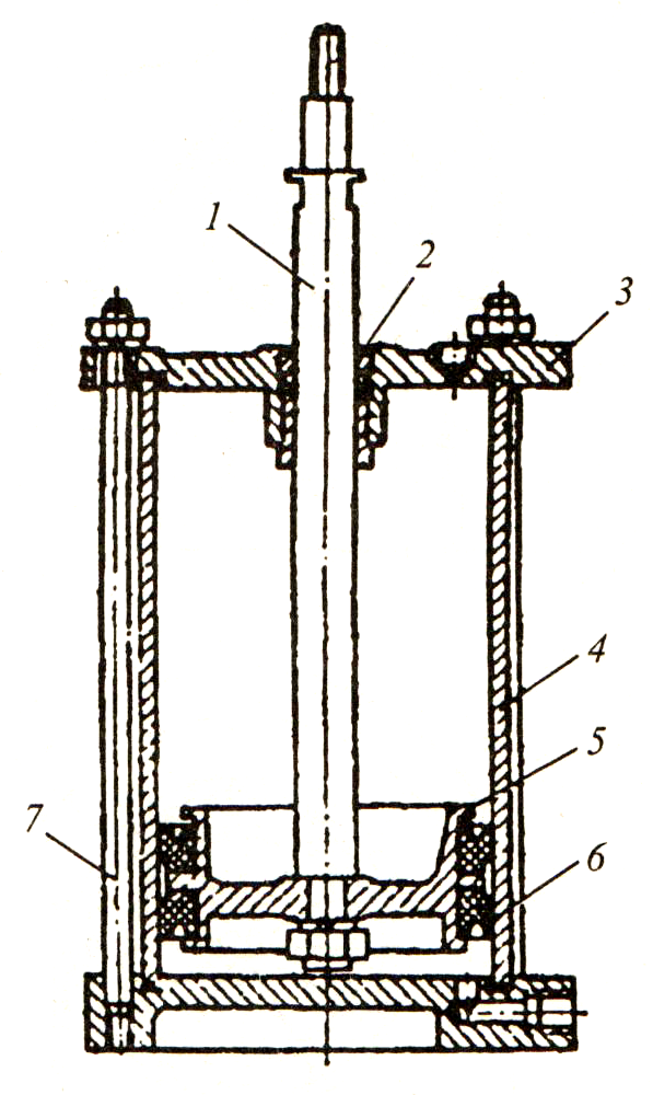
The remote position indicator DUP is designed to transmit information about the position of the regulatory body in the control system to the operator's shield.
The readings of the IP measuring device included in the measuring diagonal of the bridge correspond to the position of the output shaft of the actuator as a percentage of the full angle of rotation of the shaft. The dupe consists of a two-section coil located on a frame made of insulating material. Inside the coil is a plunger made of ferromagnetic material. The top section of the coil has a resistance of 21 ohms and the bottom section has a resistance of 22 ohms. The number of turns of the upper and lower sections is the same. When the signal of measuring information is transmitted remotely, the sections of the coil are included in the bridge measuring circuit (Figure 6.2). The technical characteristics of the DUP are summarized in table 13.
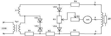
Figure 6.2 - Schematic diagram of the DUP
Table 13
6.4 Non-contact reversing starter
Contactless reversing starter type PBR-2 is designed to control an asynchronous single-phase capacitor electric motor, which is used as drives for an actuator type MEO-25 / 10-0.25.
The circuit diagram of the PBR-2 starter is shown in Figure 6.3.
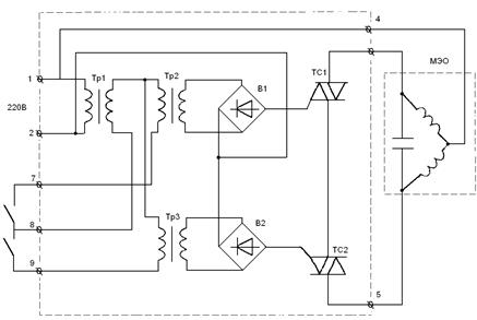
Figure 6.3 Schematic diagram of the PBR-2 starter
PBR-2 consists of terminals to which control signals are received, two thyristor switches. The motor winding is de-energized. Rectifiers that are designed to turn on one or another thyristor key. Isolating transformers, they receive voltage from rectifiers. The starter has a special output for controlling the MEO electromagnetic brake.
The technical characteristics of the PBR-2 starter are summarized in Table 14.
Table 14
6.5 Regulator
A round rotary damper is used as a regulating body. It serves to control the flow of gas and steam in pipelines of large diameter, when small pressure losses are acceptable.
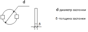
Figure 6.4 - Regulatory body
6.6 Actuator
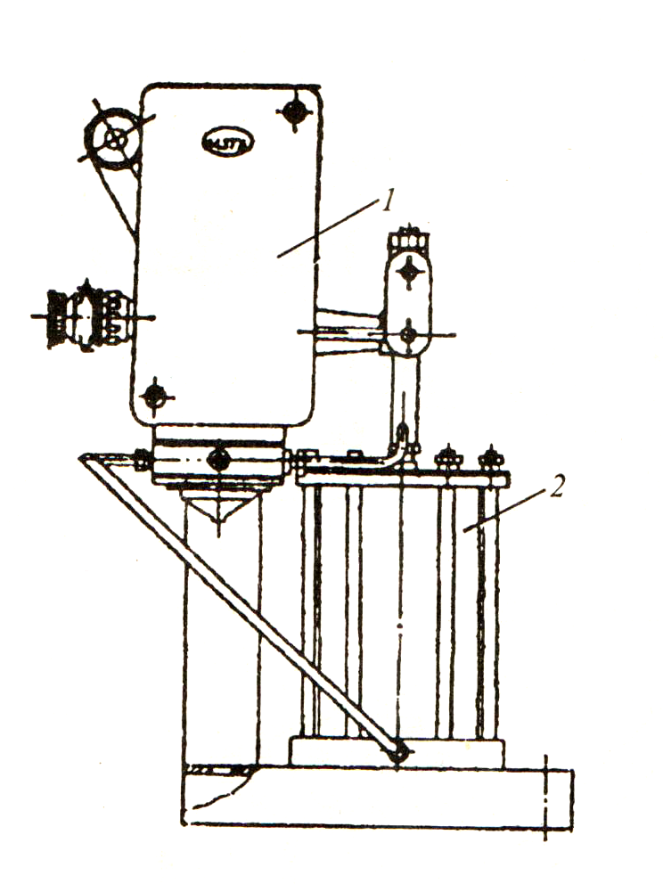
To move the regulating body, an electric single-turn actuator type MEO-25 / 10–0.25 is used
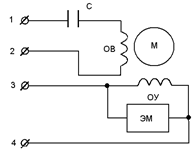
Figure 6.5 - Scheme of the actuator
At terminals 1 and 2, the ends of the excitation windings are brought out, in series with which the capacitor is connected. The control winding is connected to terminals 3 and 4, and the brake solenoid is connected in parallel with the control winding.
When the excitation winding is turned on, the motor rotor starts to rotate, and through the drive it controls the regulating body.
Actuator Specifications
МЭО-25/10–0.25 are given in Table 15.
Table 15
7. Description of the adopted scheme for monitoring and regulating the system
7.1 Air humidity control in the pre-curing chamber
To determine the air humidity in the hardening chamber, a psychrometer is used, which consists of two platinum thermometers “dry” and “wet” (pos. 1a). The "dry" thermometer is located in the measuring medium and measures the air temperature. "Wet" Between these thermometers there is a psychrometric difference in their readings. The measuring circuit of the psychrometer consists of two bridges with two common arms (pos. 1b). "Dry" TSP in one shoulder of the bridge, "wet" in the other. From the bridge circuit, the signal is fed to KSM2 (pos. 1c).
7.2 Temperature control in the curing chamber
To control the temperature in this zone, TCM is used as a primary transducer - a copper resistance thermometer (pos. 2a), it converts thermal energy into the electrical resistance, which is supplied to KSM2 - a self-recording compensator with a bridge circuit (pos. 2b), on the display of which the temperature value is displayed.
7.3 Monitoring the pressure of the heating medium in the steam line
To control the pressure in the steam line, we use the Metran-100DI pressure sensor (pos. 3a) as a primary transducer, which generates a current signal and sends it to the secondary device KSU2 - a self-recording compensator with a unified output signal (pos. 3b). The compensator shows the pressure value.
7.4 Pressure control in the steam line
To control the pressure in the steam line, we use the Metran-100DI pressure sensor (pos. 4a) as a primary transducer, which generates a current signal and sends it to the secondary device KSU2 - a self-recording compensator with a unified output signal (pos. 4b). The compensator shows the pressure value. Further, the unified signal is sent to the Remikont R-130 regulator, which regulates the steam supply to the conveyor (pos. 4c).
The choice of automatic or remote (manual) control is carried out by the key for selecting the mode of the PV1–10 type (pos. 4d). Manual control is carried out by a toggle switch type TV1–2 (pos. 4 f.). In case of inequality of the controlled temperature with the set one, in the R-130 control device, a mismatch signal is generated according to the proportional (P) control law and is fed to the reversing starter.
The reversing starter type PBR-2 (pos. 4g) includes an actuator type MEO-4 / 10-0.25 (pos. 4h) which actuates the regulating body (damper) (pos. 4 i.), which is responsible for supplying steam . The position of the regulatory body indicates the remote indicator of the position of the DUP (pos. 4d).
7.5 Temperature control in the hardening pool
To control the temperature in the hardening pool, TCM is used as a primary transducer - a copper resistance thermometer (pos. 5a), it converts thermal energy into electrical resistance, which is supplied to KCM2 - a self-recording compensator with a bridge circuit (pos. 5b), on the display of which temperature value.
7.6 Control of the heating medium flow (steam)
To control the flow rate of the coolant, we use the narrowing device DK6-Du (pos. 8a) as a primary converter, with the help of which a pressure drop is formed. With the help of impulse tubes, the pressure drop is fed to the differential pressure gauge DM-3574 (pos. 8b), where the pressure drop is converted into an electrical signal. The signal is fed to the secondary device KSD2 - a self-recording compensator with a differential transformer circuit (pos. 8c), which registers readings.
8. Safety and fire fighting equipment in the operating conditions of the system
Safety measures include organizational and technical measures and means to prevent the impact on workers of harmful production factors.
8.1 Electrical safety
When automating air curing conveyors, it becomes necessary to connect electrical installations to the mains.
Electrical injury prevention is an important task of labor protection, which is implemented in production in the form of a system of organizational and technical measures that protect people from electric shock.
The danger of operating electrical installations is determined by the fact that current-carrying conductors (or machine bodies that are energized as a result of insulation damage) do not give danger signals to which a person reacts. The reaction to an electric current occurs after it passes through human tissues.
The degree of damage to a person depends on the type and magnitude of the voltage and current, the frequency of the electric current, the path of the current through the person, the duration of the current, and environmental conditions.
As practice shows, saving a person is possible if the time during which a person is under the influence of electric current does not exceed 4 ... 5 minutes.
The causes of electrical injury are:
1) the appearance of voltage on parts of installations and machines that are not energized under normal operating conditions (cases, panels, etc.);
2) the appearance of a step voltage on the surface of the earth, as a result of the short circuit of current-carrying wires to the ground.
Other reasons include uncoordinated and erroneous actions of personnel, leaving the electrical installation energized without supervision, and a number of other organizational reasons.
The following electrical safety measures have been developed in production.
Protective grounding should ensure the protection of people from electric shock when touching metal non-current-carrying parts of the equipment, which may become energized as a result of damage to the insulation. Protective grounding is performed by deliberate electrical connection (by metal conductors) of non-current-carrying parts of electrical installations with "ground" or its equivalent.
Protective shutdown is a fast-acting protection system that automatically (for 0.2 or less) turns off the electrical installation when there is a danger of electric shock to a person in it. It is used in cases where it is impossible or difficult to carry out protective grounding.
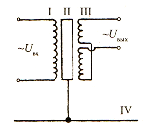
Short circuit protection between transformer windings - when automating tunnel ovens, devices are used that consume low voltage. For this, step-down transformers are used.
As a means of protection, grounding of the neutral of the secondary winding of the transformer is used, which is performed in the form of a blind connection to the ground, or the neutral is connected to a breakdown fuse.
Before carrying out electrical repair work, the following activities are carried out: a work permit is issued; repairs are carried out by at least two workers; turn off the power supply; take out fuses; short-circuit the current-carrying wires (after removing the voltage); current-carrying (short-circuited wires or parts of an electrical installation) are grounded.
A warning poster “Do not turn on - people are working” is posted on switchgears, knife switches.
8.2 Fire safety
Fires occur for various reasons and in some cases cause significant material damage, and sometimes lead to death.
The air hardening conveyor belongs to category B in terms of explosion hazard.
The enterprise must organize training for all workers and employees in fire safety rules and actions in case of a fire. Persons who have not been instructed on compliance with fire safety measures are not allowed to work.
For an air hardening conveyor, it is allowed to design one emergency exit if the distance from the most remote workplace to this exit does not exceed 25 m and the number of workers in a shift is not more than 50 people.
And in the event of a fire, fire extinguishers of types are used:
- OU-2 (carbon dioxide fire extinguisher 2 liters);
- OP-5 (powder fire extinguisher 5 liters).
9. Calculation of special automation devices
To regulate the pressure parameter, a round butterfly valve is used as RO. The round butterfly valve is installed on a pipeline with a diameter equal to Dy=120 mm. The damper is made of steel 20XM, steel density p=7.85 kg/dm 3 .
To move a circular butterfly valve, it is necessary to perform a force calculation in order to determine the displacement force that the actuator must develop.
Butterfly valve has the following characteristics: diameter and thickness.
Damper diameter d, mm, calculated by the formula
|
where D y is the diameter of the pipeline, mm.
d=0.95*120=114 mm=11.4 cm
Where n ed is the number of revolutions of the gearbox output shaft, rpm.
In the general balance of atmospheric air pollution, the share of asbestos-cement materials industry enterprises accounts for more than 8% of pollution. At these enterprises, dust is emitted in large quantities during operation. technological equipment. Many technological processes are accompanied by the release of harmful gases.
There are two engineering protection methods environment from pollution:
1) creation of a waste-free technology that operates without emissions of harmful substances into the environment;
2) the use of a set of technical means for localizing sources of harmful emissions and deep purification of exhaust gases.
However, the creation of waste-free technology is a very complex task and cannot be completely solved.
10.1 Technical means for air purification
Purification of dusty emissions into the atmosphere has its own specific features. In this case, the airborne dust can have a wide range of particle sizes, and its concentration can be very high. It is cleaned from dust with the help of dust collectors and filters.
Cyclones are more efficient dust collectors based on the separation of dust particles from the air due to centrifugal forces. The efficiency of cyclones is 80…90%.
In bag filters, air is cleaned from dust by filtering it through a fabric sewn in the form of separate sleeves that are built into the airtight filter housing. The cleaned air is sucked out of the filter and released into the atmosphere. The dust collection efficiency is quite high from 95 to 99%.
At low concentrations of dust in the gases being cleaned, bag filters are the only purification stage, and at high concentrations, cyclones are installed in front of them.
Wet dust collectors are the widest class of equipment designed for air purification. In these devices, due to the contact of the liquid with dust particles, the latter are wetted, weighted and removed from the devices in the form of sludge.
In production, a cyclone with a water film is used. Dust particles, as in a conventional dry cyclone, are thrown to the walls of the apparatus under the action of centrifugal forces. Here they are carried away by water and are carried away to the bunker. The presence of a water film increases the dust collection efficiency of such cyclones compared to dry cyclones and is on average from 99.0 to 99.5%.
Foam dust collectors have high dust collection efficiency when cleaning the air from wettable dust. The degree of air purification is from 95 to 95.99%.
Electrostatic precipitators are used to clean ventilation and industrial emissions into the atmosphere. The operating principle is based on the phenomenon of gas ionization in the interelectrode space. They have high efficiency up to 99.9%. Electrostatic precipitators are economical and allow to purify gases at high temperatures.
Absorption (adsorption) methods are based on the absorption of gaseous impurities by various liquids (solid absorbers). Their efficiency is from 99.5 to 99.8%.
Methods of high-temperature combustion (from plus 950 to plus 1100°C) of harmful impurities are used when their concentration in the exhaust gases is high and they have the ability to oxidize. Combustion of gaseous impurities is most often carried out in flame furnaces.
Low-temperature catalytic afterburning (from plus 200 to plus 300 °C) is used at low concentrations of hot impurities. Afterburning is carried out in special installations in the presence of a catalyst. In this case, toxic substances are oxidized, turning into other, harmless substances.
If the use of a complex of technological and sanitary and hygienic measures fails to reduce the pollution of exhaust gases to the required levels, then such gases have to be emitted into the upper layers of the atmosphere in order to maximize their dispersion and reduce the harmful effects on the environment.
Conclusion
The main goal of automating production processes is to ensure savings in raw materials and fuel and energy resources, reducing manual operations, improving the work of service personnel, improving conditions for managing units, processes and production in general, i.e. improvement of technical and economic indicators of the technological stage, workshop, enterprise. At the same time, when creating an automation system, it is necessary to make expenses for research and development, design work, additional capital investments for the means used, for the construction of premises for accommodating a computer center (CC), instrumentation services and automation equipment. These costs should be commensurate with the enterprise's capabilities in terms of the efficiency of their use.
Automation of production is a necessary, main part of any technological process.
The purpose of automation is to ensure the production of high quality products with optimal technical and economic performance of the equipment. The main influence in the organization of production control is given to the mandatory use of control data for the operational management of production processes.
As a result of the commissioning of this system, the following has been achieved: the reduction of manual operations improves the working conditions in the management of units, processes and production in general, i.e. the technical and economic indicators of the enterprise's workshop are increased.
The introduction of automation means leads to an increase in the economic effect, which is the totality of all production resources of living materials.
List of sources
1 Goroshkov, B.I. Automatic control: Textbook for students. Institutions prof. education "Academy" / B.I. Goroshkov. - M.: IRPO: Publishing Center, 2003. - 304 p.
2 Evstafiev, K.Yu. Automatic regulation: Textbook./ K.Yu. Evstafiev, I.I. Goryunov, A.A. Rulnov. – M.: INFRA-M, 2005.-219 p. – (Secondary vocational education).
3 Kelim, Yu.M. Typical elements of automatic control systems: Textbook for students of institutions of secondary vocational education. - M: FORUM: INFRA-M, 2002. - 384 p.
4 Klyuev, A.S. Design of automation systems for technological processes: Reference manual / A.S. Klyuev, B.V. Glazov, A.Kh. Dubrovsky, A.A. Klyuev. - M: Energoavtomitizdat, 1990. - 464 p.
5 Shishmarev, V.Yu Typical elements of automatic control systems: Textbook for environments. prof. Education /V.Yu. Shishmarev. - M.: Publishing Center "Academy", 2004.-304 p.
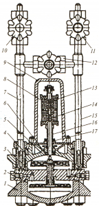
Unified automation of microboilers (AMCU) is designed to automatically maintain the steam pressure within the specified limits, as well as to maintain the water level in the boiler within the specified limits. Provides protection and alarm. It is used on boilers of type E-0.4 -1 / 9G (MZK) and boilers of type E-1-2.5 / 9-1 G (MMZ).
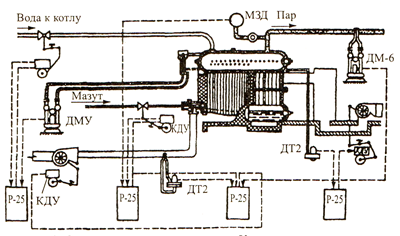
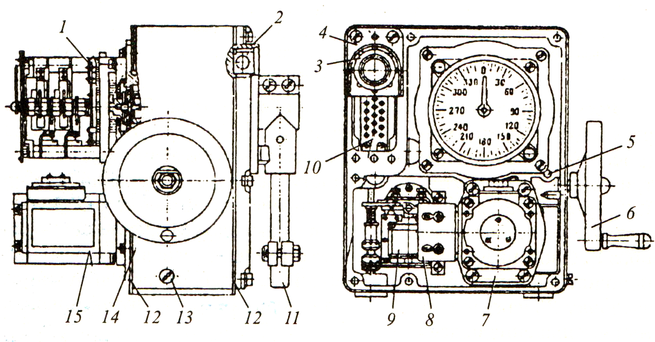
| A. AMCU automation control devices: 1. Bellows pressure switch DD-10-20K. 2. EIM-1 air damper. 3. EIM-2 vacuum dampers. 4. Level column with remote control level sensors B. AMCU automation safety devices: 5. Membrane sensor-relay for pressure and thrust DNT-100. 6. Membrane pressure sensor-relay DN-250-10K with a setting limit of 180~220 kgf/m2. 7. MDN-250-10K with a setting limit of 80~120 kgf/m2. 8. Membrane air sensor. 9. Reference electrode. C. Auxiliary devices of AMCU automation: 10. Control unit BU-M. 11. Call. 12. BPG combustion power supply. 13. Ignition transformer. G. Gas equipment and automation fittings AMKO: 14. Control valve. 15. Faucet on the safety candle. 16. Crane on impulse to the power supply unit for combustion of the BPG. 17. Working valve. 18. Burner type G-1.0. D. Thermal mechanical equipment of AMCU automation: 19. Boiler. 20. Main steam valve. E. Symbols on the AMCU automation scheme: 21. Smoke exhauster. 22. Fan. 23. Feed pump. 24. Ignition electrode. 25. Shut-off valve. 26. Combined valve of large and small combustion. Also see the purpose of gas pipelines by color - indicated on the AMCU automation diagram. |
|
The principle of operation of automatic control of the combustion process.
The steam pressure in the boiler drum is measured by a sensor of the DD-10-20K type (see Fig. item 1). When it reaches the upper set value, DD-10 will feel it and send an electrical signal to BU-M, and BU-M gives a command to close the combined valve of large and small combustion. The valve closes, but the combustion gas continues to flow through the holes in the valve disc, which is 40% of the maximum amount. At the same time, the BU-M sends commands to the EIM-1 (2) and EIM-2 (3) to cover the air damper and the flue gas gate to the limit stops, which will provide 40% of the combustion air supply and 40% of the flue gas removal . The boiler switched to low combustion. At the same time, the temperature in the furnace begins to decrease, and at the same time, the steam pressure at the outlet of the boiler decreases. When the steam pressure reaches the lower set value, this will be felt by the DD-10 sensor, which will give an electrical signal to the BU-M, and it will give a command to open the combined valve of large and small combustion, and at the same time commands will go to EIM-1 and EIM- 2 for 100% opening of the air damper and flue gas damper. The boiler switches to high combustion, etc.
The principle of operation of automatic protection type AMCU.
When any of the parameters reaches the pre-emergency value, this will be sensed by the corresponding device and will give an electrical signal to the CU-M. The light and sound alarms are switched on. The sound signal is not removed. Light - the "Normal operation" light goes out. When the boiler is disconnected from a drop in the level below the NDU, the “no water” light comes on, the BU-M sends a command to the shut-off valve (closing). The gas supply stops, the boiler is turned off. The gas supply also stops when at least one safety device fails and when the power goes out.
The principle of operation of automatic control of the supply of the boiler with water.
As a result of steam consumption, the level in the boiler drum begins to decrease. When the level reaches the lower set value, a signal is sent from the level gauge column to the CU-M, and the CU-M gives a command to turn on the feed pump. The water level in the drum begins to rise and when it reaches the upper set value from the level gauge column, the CU-M receives a signal, and the CU-M gives a command to stop the feed pump.
Automatic control system for boilers KPA-500. The boiler automation system (see I) has two steam pressure control devices LKD-1 and AKD-2, which directly control its operation depending on the steam pressure.
Automatic steam pressure control devices AKD-1 and AKD-2 are adjusted at the place of operation of the boiler, depending on the upper and lower limits of steam pressure necessary for the normal operation of consumers, as well as depending on the steam flow rate, and the automatic device AKD-2 is adjusted to a slightly lower pressure steam than the AKD-1 automatic machine, which turns off the boiler when the upper steam pressure is reached.
If the steam pressure at the outlet of the boiler increases above the pressure set on the AKD-2 pressure control machine, the AKD-2 machine will turn off the second fuel nozzle, move the air throttle and switch the feed pump electric motor to operate the boiler at half capacity.
At this capacity, the boiler will operate until, due to an increase in steam consumption, its pressure drops below the pressure set on the AKD-2 machine to turn on the second nozzle and the corresponding units to operate the boiler at maximum performance.
The regulation of the performance of the feed pump is ensured by the use of a two-speed electric motor to drive it.
If, when the boiler is operating at half capacity, the steam pressure increases above the pressure set on the AKD-1 machine, the AKD-1 machine will also turn off the first nozzle, and the boiler will remain off until the steam pressure drops below the pressure set on the machine AKD-2 to turn on, after which the boiler will restart automatically according to the initial cycle.
In the event that the flue gas temperature exceeds 210 °C, the boiler is automatically switched off. The impulse for switching off is given by a thermostat installed in the pipe for removing combustion products from the boiler.
KPA-500 boilers provide for automatic shutdown of the boiler in the following cases: steam temperature rises above the set value (190°С); exceeding the working steam pressure of more than 0.02 MPa (0.2 kgf / cm2); stop burning fuel; flue gas temperature increase over 210 °С; breakage of one (controlled) or two feed pump drive belts. Safety valve steam boiler adjusted to 0.93 MPa (9.3 kgf/cm2).
In gaseous fuel boilers, in addition to the above cases, automatic shutdown is provided when the gas pressure drops by 300 Pa (30 mm of water column) below the permissible value and when the air pressure in front of the burner drops by 100 Pa (10 mm of water column) below the set.
Automatic control system for low power boiler AMK-U
Integrated automation of the operation of steam boilers with a steam output of up to 1.6 t/h and hot water boilers operating on liquid and gaseous fuels is carried out by the AMK-U system, designed to operate in closed heated rooms in the temperature range from +5 to +50 C at relative humidity up to 80%. Eight modifications of the system are provided depending on the application, type and type of fuel burned.
Modifications of the AMK system provide two-position automatic regulation of steam pressure and water level in the boiler drum within specified limits, proportional air supply and maintenance of rarefaction in the furnace in accordance with fuel consumption, as well as protection of the boiler in case of water leakage, excess steam pressure in excess of the allowable, when supply is stopped air and electricity, extinguishing the flame of the burner or nozzle, cessation of thrust. When the protection is triggered by any parameter, the fuel is turned off and an audible alarm is activated. In case of water leakage, in addition to the sound alarm, the light panel "No water" is turned on. Automatic protections are built in such a way that after they are triggered by any emergency parameter (except for the flame extinguishing) and it is restored to normal, the self-starting of the boiler is excluded: operator intervention is necessary.
The power source of the automation system is an alternating current network with a voltage of 220/380 V.
Gas is supplied to the boiler through the gas valves of "large" (K-70) and "small" (K-40) combustion. Liquid fuel is supplied to the boiler in the same way, through two solenoid valves. The valves are controlled by a block of solenoids (a "large" combustion solenoid and a "small" combustion solenoid).
The steam pressure is controlled by a two-position regulator. The impulse for steam pressure comes from a sensor - a pressure switch. During normal operation of the boiler, when the steam pressure is within the specified limits, the contact of the sensor B4 (39) is closed, the relay winding P10 is energized and its contact P10 / 1 closes the power circuit of the solenoid of the "large" combustion valve Em4 (Em8). Excess pressure on the boiler in excess of the protection triggering setting causes contact B4 to open, relay P10 to de-energize, and power to the solenoid of the "large" combustion valve Em4 (Em8) is turned off by contact P10/\. The operation of the boiler continues with the valves of the igniter Em5 (EmT) and "small" burning Emb. Turning off the "large" combustion valve entails a decrease in gas consumption up to 40% (on liquid fuel up to 50%) and, as a result, a decrease in steam pressure in the boiler. When the steam pressure in the boiler drops to the value determined by the sensor setting, contact B4 closes, and the "large" combustion valve Em4 (Em8) is turned on again. This ensures the operation of the boiler in the load range of 40-100% (on liquid fuel 50-100%). The frequency of opening and closing of the "large" combustion valve is determined by the nature of the change in the load of the boiler and the return zone of the contact device of the pressure sensor.
The water supply to the boiler is regulated by a two-position level controller, the level sensors of which are two electrodes (E1 and E2) in the level gauge column. One sensor is installed at the lower adjustable level (LRU), the other - at the upper adjustable level (ASU).
If the boiler is powered by an individual feed pump with M2 electric drive, the function executive body The power regulator is performed by a magnetic starter RZ, which controls the operation of the electric motor M2 of the feed pump. With a low water level in the boiler, the level switch P11 is de-energized, the RZ magnetic starter is switched on by contacts P11 / 2, and the feed pump operates at nominal capacity. As soon as the water level reaches the upper adjustable level of the ASU, the level relay P11 turns on and the contact P11 / 2 breaks the power supply circuit of the RZ magnetic starter, turning off the drive of the feed pump. The water supply to the boiler is stopped. Relay P11 is blocked by contact P11/1. The water level in the boiler drum during its operation gradually decreases, and when it drops below the NRU, the RP relay is de-energized and the feed pump is turned on. Regulation of the pump supply by the AMK automatic system is not provided, the water level in the drum is regulated from the lower to the upper adjustable levels by turning the pump on at nominal capacity and turning it off.
The AMK automation system provides for a proportional change in the air supply with a change in fuel consumption. This is achieved by electrically blocking the control of the "large" combustion valves Em4 (Em8) and the electromagnetic actuator Em1, which opens the air damper of the fan. The maximum fuel consumption corresponds to the maximum air supply. The actuator Em1 of the air damper drive and the solenoids of the "large" combustion valve Em4 (Em8) are controlled by the contacts of the relay P10.
In boilers operating on liquid fuel, fuel is heated to a temperature of 80-105 ° C to ensure fine atomization and stable combustion. Heating is carried out by an electric heater. Fuel temperature control is provided by automatic switching on and off of the heater. As a temperature sensor, a combined relay KRD-1 (KRD-2) is used, which controls its VZ contact with the power supply circuit of the P8 liquid fuel temperature relay. If the temperature of the liquid fuel is insufficient, the OT contact of the temperature sensor closes, the P8 relay is activated and the electric heater is turned on. As soon as the fuel temperature reaches the upper adjustable value, the VZ contact opens, relay P8 is de-energized and the electric heater is turned off.
The boiler is put into operation remotely by pressing the "Start" button, accompanied by the operation of the magnetic starter P1, the supply of voltage to the automation circuits, and the switching on of the blocking relay P7. Magnetic starters RZ and R4 turn on the electric motors of the M4 fan, the Ml smoke exhauster (if any), and the M2 feed pump. The signal lamps "Voltage" and "No water" light up (if its level in the boiler drum is below the lower emergency level), the furnace is ventilated, and the circuit is prepared for fuel supply and ignition. After filling the boiler with water, the "No water" display goes out, and relay P12 is activated. After closing the contacts of the B5 limit steam pressure sensor, the B8 air pressure sensor, the B9 vacuum sensor in the furnace, the B10 emergency gas pressure decrease sensor, the HV gas overpressure sensor, and 10-15 seconds after the first pressing of the "Start" button, relay P5 is activated, the boiler ready to fire. When the "Start" button is pressed again, after thorough ventilation of the furnace and gas ducts, the boiler automatically ignites. Relay P9 is activated, and for boilers operating on liquid fuel, the magnetic starter P2 of the fuel pump electric motor is activated, and the contact of the liquid fuel pressure sensor BT closes. When the "Start" button is turned off (with all normal parameters), relay P9, blocking with its contacts, turns on the circuit of blocking relays and protection P14, P15.
Ignition of the fuel occurs with a stable breakdown of the gap of 6-10 mm on the electrodes with a voltage of 10 kV, created on the secondary winding of the transformer Tr2. In the automation circuit of gas-fired boilers, one ignition transformer is provided, and for liquid-fuel boilers, two transformers connected in parallel. The ignition circuit is controlled by the flame control relay P5. If the flame in the furnace goes out, relay P5 is activated and turns on the ignition circuit. Along with this, the thermal time relay RT1 is switched on, and an attempt is made to automatically ignite within 25-40 s.
In boilers operating on gaseous fuels, a spark from the ignition transformer is supplied to ignite the gas leaving the igniter when the Em5 valve is open, and on liquid fuel - directly to ignite the fuel when the small combustion valve Em7 is open. The appearance of a torch is accompanied by the activation of the actuator Em8, which fully opens the air damper. On gas fuel, the high and low combustion valves open, and on liquid fuel, the high combustion valve opens. Upon successful start, the signal lamp "Normal operation" lights up. Stop the boiler by pressing the "Stop" button.
The protection of the boiler when the steam pressure exceeds the sensor set by the setting (relay DC-10-20K) occurs when the contact B5 opens and the protection circuit is triggered, the relays P14 and P9 are de-energized, and the fuel supply is stopped.
To protect the boiler from water leakage, a low alarm level sensor E4 is installed in the level gauge column, which is connected to the power supply circuit of relay P12. An emergency lowering of the water level is accompanied by a break in the supply circuit of the relay P12, the relay coil is de-energized, the protection circuit is activated, the relays P9, P14 are de-energized, the fuel supply is stopped, and the feed pump is turned off.
The boiler is not protected from overwatering. In order to avoid accidents associated with overfeeding the boiler, the automation circuit provides for an alarm of the upper alarm level, the sensor of which is the EZ electrode in the level gauge column.
To protect the boiler from an emergency decrease in vacuum, a sensor (pressure and draft relay DNT-100) is used, which is adjusted to a certain draft. When the thrust decreases, the sensor is triggered, its contact B9 breaks, the protection circuit is activated, and the relays P9, P14 are de-energized.
The boiler protection circuit in case of an emergency decrease in liquid fuel pressure was built using the pressure switch RD-12 as a sensor with setting limits from 0.5 to 2.0 MPa (from 5 to 20 kgf/cm2). The decrease in fuel pressure below the protection operation setting is associated with the opening of the relay B7 contact, which causes the protection circuit to operate and de-energize the relays P9, P14.
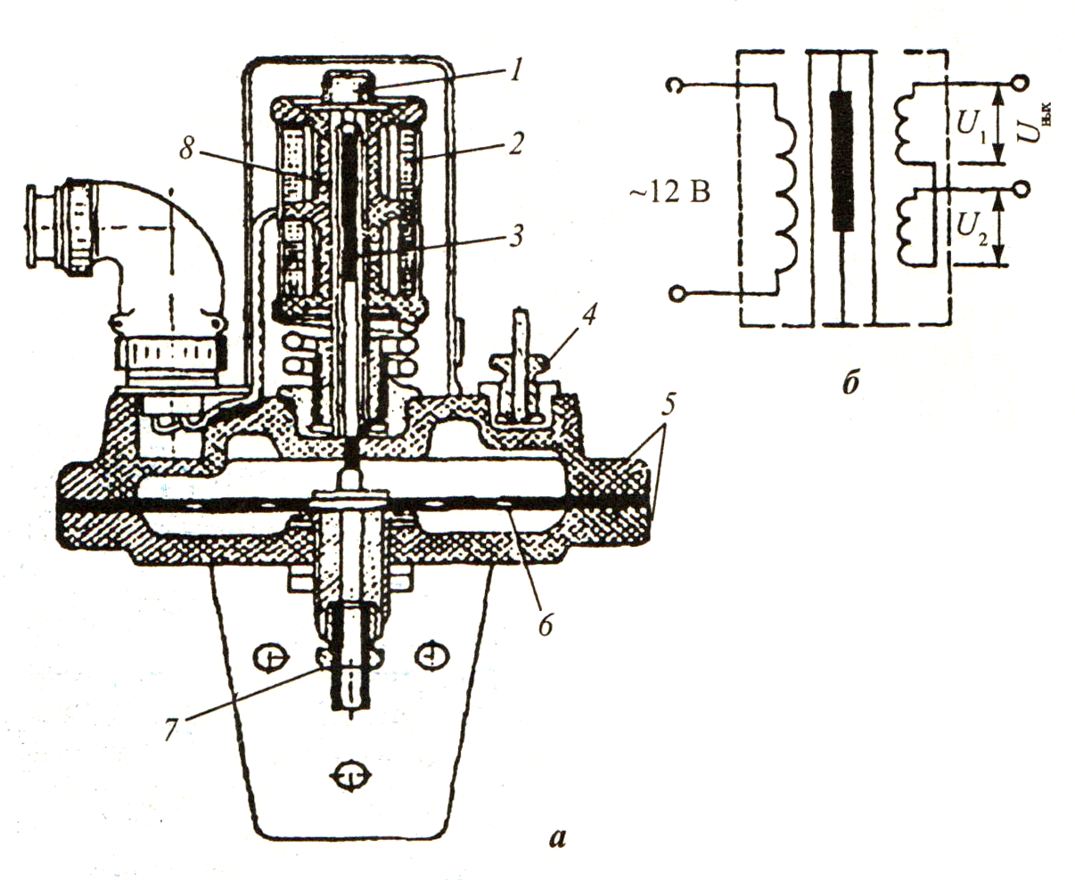
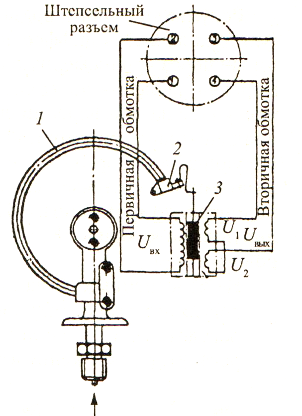
Flame control device in automatic system AMK presents a two-stage amplifier constant voltage on a double triode 6N6P. A sensitive element is connected to the input of the circuit to the terminals /, 2. The output of the circuit is the load of the P5 flame control relay, the contacts of which control the switching on and off of the gas and oil valves and the ignition system. In gas-fired boilers, the sensitive element is the E5 control electrode, which is installed in the furnace isolated from the burner body and the boiler in such a way that its end is washed by the flame of the burner (igniter)
When operating boilers on liquid fuel, a photocell Eb and a photoelectric sensor (PD) are used as a sensitive element. The flame control device protects the boiler in case of emergency flame failure.
Automation system KSU-2P
A set of control tools (CCU) (40) for steam boilers with a steam output of up to 2.5 t/h, operating on gaseous and liquid fuels, was developed to replace the AMK-U automation system. A set of control tools with a different combination of instruments and devices allows you to automate the operation of boilers, regardless of the thermal scheme and type of fuel burned.
Boilers with natural circulation, forced air supply and forced draft are equipped with KSU-2P-1 controls, the same boilers with pressurized furnaces are equipped with KSU-2P-2 controls. The KSU-2P-3 kit is designed to equip once-through boilers with a pressurized furnace. The electrical power supply of the set is carried out from a three-phase AC network with a voltage of 220/380 V or 127/220 V.
The set of controls is designed to operate at an ambient temperature of +5 to +50 °C and a relative humidity of 30 to 80% over the entire operating temperature range, provides regulation of:
water level in the boiler drum within the range from the lower adjustable level (LRL) to the upper adjustable level (ASL) according to the signals from the sensor of the level gauge column;
supply of fuel and air in the range of 50-100% according to the signal of the steam pressure sensor;
fuel oil temperature in the range of 80-95 °C according to the signals of the fuel temperature control sensor.
Automatic protection and interlocks ensure the shutdown of the boiler and blocking its start-up when the water level in the boiler drum drops below the lower emergency level (LAL); increase in steam pressure in the boiler in excess of the allowable; decrease in air pressure behind the damper; lowering the gas pressure in front of the valve blocks or its emergency increase; decrease in fuel oil temperature or its emergency increase; lowering the fuel oil pressure in front of the safety valve; extinction of the flame of the main torch or the igniter flame.
Light signaling is provided by green light: "Network", "Boiler on", "Regulation"; red light: "The boiler is switched off" with an explanation of the reason for the shutdown; Air pressure low, Steam pressure high, Water level low, Water level high, Fuel pressure low, Gas pressure high, Oil temperature low, Oil temperature high, No flame."
Automation generates an information signal to the control panel about the end of ignition and about a violation of the normal operation of the boiler or set.
Structurally, the KSU-2P kit is made in the form of two separate blocks: a control and signaling unit (BCS) and a block of switching elements (BKE).
The BUS block contains all the elements that provide start-up and stop control, regulation, protection, and signaling. Signal lamps, controls and controls are located on the front panel.
In the BKE block there are: relays and starters, an automatic circuit breaker, a block of the ignition device of the ignition circuit.
The electrical connection of the BUS and BKE blocks to each other is carried out using a connecting cable ending in plugs of RSHA type connectors, and the blocks are connected to external devices through terminal blocks located on the rear wall of the BUS block and in the lower part of the BKE block.
The set contains the following main functional devices: program control and regulation device; blocking and signaling protection device; power amplifiers; power device.
Schemes of devices for program control and regulation, protection and signaling are built on the elements of binary logic.
The device for program control and regulation forms a sequence of commands for controlling the executive bodies and drives during the operation of the boiler. When the startup program is turned on, the device automatically generates the necessary sequence of commands to turn on the protection devices according to individual parameters and states.
The protection and blocking device perceives the signals of the protection sensors and, in the event of an emergency value of any of these signals, ensures the shutdown of the boiler plant and blocking its start-up (by influencing the control units), as well as issuing commands to turn on the corresponding alarm devices. The activation of protection and blocking devices is carried out during the start-up of the boiler plant according to signals received from control devices.
The alarm device generates commands to turn on the light and sound signals based on the impulses of the commands of the protection and blocking devices. On the front panel of the BUS block there are buttons for checking the serviceability and turning off the light and sound alarms. The working alarm is controlled by signals from the program control and regulation device.
Power amplifiers are used to amplify the power of the control signals generated by the control devices and fed to the actuators of the boiler plant.
Advantages of the KSU-2P automation system compared to the AMK-U system:
the KSU-2P system provides for complete automation of the boiler with the ability to control and manage from the control room;
the KSU-2P system provides protection, emergency and working signaling with memorization of the root cause of the boiler shutdown;
the KSU-2P system improves the reliability of equipment operation due to a more advanced circuit using highly reliable non-contact discrete elements.
Automatic regulation of the boiler operation parameters is carried out by two-position regulators, the principle of operation of which is similar to that of the regulators of the AMK-U system.
Control device KURS-101
In the automation schemes for steam boilers operating on gaseous or liquid fuels, control devices KURS-101 (41) are used. The devices are designed to operate in the temperature range from +5 to +50 °C at relative humidity over the entire operating temperature range of 30-80%. The device is powered from a three-phase alternating current network with a voltage of 220 V, the power consumption does not exceed 220 V A.
The control device KURS-101 provides: automatic start and stop of the boiler; pre-ventilation of the furnace; automatic ignition of the burner; blocking required during the start-up period; positional automatic control of the thermal power of the boiler; automatic protection in emergency situations; working and emergency signaling; formation of an emergency signal to the control room.
The control device is structurally made according to the block-module principle and includes a control and signaling panel (PSU), a cabinet with a swivel frame and a cabinet of magnetic starters.
The control and signaling panel (PSU) combines the C-02 signaling module with indicator lamps; pre-ventilation; ignition; pilot valve; torch; water temperature (limit); steam pressure (limiting); post-stop ventilation.
The indicator lamp "Operation" indicates the normal operation of the device, the indicator lamps "Gas" and "Mazut" indicate the type of fuel on which the device is turned on.
The panel also includes indicator lamps "Water" and "Steam", signaling the operating mode of the boiler, on which the device is turned on; indicator lamp "Voltage", signaling the presence of voltage of the electric power source at the input to the device; indicator lamp "AVR of the feed pump", signaling the automatic switching on of the backup feed pump "a (when the boiler is operating in steam mode); indicator lamp "Emergency" - about the onset of an emergency mode for any parameter.
The S-01 signaling module with indicator lamps signals the root cause of the emergency shutdown of the boiler: the level is low; level is high; gas pressure in front of the regulating body is high; fuel oil temperature is low; fuel pressure in front of the shut-off valve is low; secondary air pressure is low; gas pressure in front of the burner is low; primary air pressure is low; there is no torch; the shut-off valve is not closed; there is no pilot flame.
The block of control buttons has a "Start" button for turning on the logic circuit of the control device and starting the boiler; button to enable "regulation ON" and disable "regulation OFF" regulation with module K-01, the button "Stop" to turn off the device and bring the circuit to its original pre-start state.
The control and signaling system includes an indicator of the type IPU of the position of the regulatory body.
In a cabinet with a swivel frame, there are: block P-11A for providing electrical power to the circuit elements; unit U-04 for controlling the motor of the MEO-4/100 actuator; unit F-03 for supplying voltage to the ignition coil bobbin (B-1) installed on the boiler burner.
The listed devices are united in the control unit BU-01. It also contains: a block of switches BP-01 for the type of fuel (gas, fuel oil), operating mode (hot water, testing of the feed pump, steam), feed pumps (No. 1, No. 2), testing and normal operation of fans, turning on and off the voltage at device input; block P-jDl relays controlling electromagnetic actuators; block B-1 for placement and inter-module mounting using plug-in connectors and harnesses.
Electric starting equipment is located in the cabinet of magnetic starters.
The boiler is started (when the power supply is on and there are no signals, the emergency state of any parameter or the limit state of the main parameter - water temperature or steam pressure) is carried out by pressing the "Start" button. After that, the actuator fully opens the fuel and air regulators (this is judged by the indications of the position indicator), the magnetic starters of the primary air (only when the boiler is operating on fuel oil) and secondary air are switched on, the countdown of the pre-ventilation time is switched on. After the pre-ventilation time (120 ± 24 s) has elapsed, the automation sends a signal to the actuator that closes the air damper and regulates the fuel supply damper to 20% opening, voltage is applied to the ignition coil B-1 and to the igniter valves.
If the igniter is not ignited within 10 ± 2 s, the "Emergency" signal appears, post-stop ventilation is switched on, the igniter valves and the ignition coil are de-energized. The duration of post-stop ventilation is 60 ± 12 s, after which the circuits of the magnetic starters of the fans are de-energized.
In the event of ignition of the igniter, voltage is supplied to the cut-off valves (on the gas and oil lines) and the B-1 ignition coils are de-energized. Ignition of the burner occurs within 7 ± 1.4 s (for gas) and 11 ± 2.2 s (for fuel oil). If during this time the ignition of the burner does not occur, the "Emergency" signal and post-stop ventilation are turned on, the igniter valves and shut-off valves on the fuel supply line are de-energized. After the post-stop ventilation time has elapsed, the magnetic starters of the fans are de-energized.
When the burner is ignited, after the end of the start-up time (35 ± 7 s), the fuel and air regulators are transferred to the 40% open position. The igniter valve coils are de-energized after 60 ± 12 s of the time of joint operation of the igniter and the burner.
The operation of the boiler in the 40% load mode continues for the time specified in the operating instructions for the boiler, which is necessary for warming up all the elements, after which the automatic regulation of the main parameter of the boiler - temperature can be turned on with the "Regulation ON" button hot water or steam pressure. Automatic regulation is carried out by moving the actuator that regulates the supply of fuel and air, in the position of 40 and 100%.
In case of achievement limit state controlled parameter, the circuit de-energizes the supply circuits of the shut-off valves on the fuel supply line, the fuel and air control elements move to the 20% open position, post-stop ventilation is turned on, after the boiler operation time, the supply circuits of the magnetic starters of the burrows are de-energized. When the signal of the limit state of the parameter is removed and the signal of the low state of the parameter is received by the control device, the circuit ensures automatic start-up of the boiler in the sequence indicated above.
Automatic regulation is turned off by pressing the button "Regulation FROM TO L", accompanied by switching the actuator to a position of up to 40% opening of the fuel and air regulators.
The boiler is switched off by pressing the "Stop" button, which is accompanied by de-energizing the circuits of the fuel cut-off valves, automatic movement of the fuel and air regulators to the 20% opening position, switching on post-stop ventilation, and de-energizing the control circuits of the magnetic starters of the fans.
If, during normal operation or during the start-up period, the control device receives a signal about the alarm condition of any parameter, the "Alarm" signal and the indicator light corresponding to the root cause of the alarm will light up, as well as the "post-stop ventilation" indicator light (except for the pressure reduction alarm). primary or secondary air, since in this case the circuits of the magnetic starters of the fans are de-energized). At the same time, the control circuits of the fuel cut-off valves are de-energized, which is accompanied by the extinction of the "Work" and "Torch" lamps; the fuel and air control elements are moved to the 20% open position (except for the primary and secondary air low pressure alarm). As soon as the post-stop ventilation time expires, the control circuits of the magnetic starters of the fans are de-energized, as evidenced by the extinction of the "Post-stop ventilation" indicator light. The "Emergency" signal is removed by pressing the "Stop" button.
Alarm system the control device provides for fixing: lowering the water level in the boiler or in the deaerator (hot water mode); increasing the water level in the boiler; increasing the gas pressure in front of the regulatory body; lowering the temperature of fuel oil; lowering the fuel pressure in front of the shut-off valve; secondary air pressure reduction; lowering the gas pressure in front of the burner; decrease in primary air pressure; extinction of the torch of the burner device; lack of closing of shut-off valves; extinction of the igniter flame.
Schemes of automatic control of steam drum boilers.
For boilers of the DKVR, DE, KE types, automatic control schemes are determined by the manufacturer's specifications and provide for automatic control of combustion processes and boiler water supply. Automatic regulation of the combustion process ensures the supply of fuel to the furnace depending on the load of the boiler, maintaining the optimal fuel-air ratio and stable rarefaction in the furnace.
The commonality of the dynamic properties of the boiler control sections allows the use of typical automatic control schemes. The most common automatic control scheme is based on the controllers of the "Crystal" system (42).
Regulation of the fuel supply to the furnace ensures that the steam output of the boiler matches the steam load. In boilers of the DKVR, DE, KE types, the role of the load regulator is performed by the steam pressure regulator in the boiler drum, which affects the change in the fuel supply and has a rigid or flexible feedback (42, 43, a). The use of regulators with hard feedback allows you to maintain the value of the controlled value with a deviation from the specified value up to 4-6%. With higher requirements for control accuracy, a controller with flexible feedback is used.
The change in pressure in the boiler drum during operation is perceived by the pressure sensor - an electric manometer MED, which issues a mismatch signal in the form of an alternating current voltage, which enters the 2UT amplifier. The 2UT amplifier turns on, depending on the sign of the pressure deviation, the corresponding relay of the 2GIM actuator (GIM-2D, GIM-2DI), which moves the fuel supply regulator - the fuel oil valve or the gas damper. Simultaneously with the operation of the actuator, a signal is generated feedback, which is removed from the feedback device (sensor) of the UOS of the GIM-2D (GIM-2DI) actuator and is introduced into the 2UT amplifier, where it is added to the main error signal. The introduction of feedback terminates the action of the regulator somewhat earlier than the pressure stabilization, taking into account the inertia of the completion of the regulation process.
Air supply regulation provides an optimal ratio between the fuel and air supplied to the furnace (optimal air excess), which ensures maximum fuel combustion efficiency in all boiler operating modes.
When operating on gas, the regulator according to the "fuel - air" scheme (43, b) receives an impulse from the gas flow to the boiler, which is directly measured by the flow meter, and an impulse from the air pressure drop, which is proportional to the air flow. The regulator acts on the guide apparatus of the blower fan. In boilers of DKVR and DE types, more than simple circuit(43,c), where the pulse on gas (fuel oil) consumption is replaced by a pulse on gas (fuel oil) pressure in front of the burners, which indirectly characterizes the fuel consumption. Such a replacement is acceptable for boilers operating with a stable vacuum in the furnace. In this case, the second impulse to the regulator will be the air pressure impulse in front of the burners. For boilers operating on liquid fuel, when measuring its flow rate with a narrowing device, the "fuel-air" scheme does not differ from the similar scheme used on boilers operating on gaseous fuel.
Sometimes in air control circuits, instead of a pulse from a fuel flow sensor, a pulse from a displacement sensor of the fuel regulator actuator is used (when operating on liquid and solid fuel). Here it should be borne in mind that the fuel consumption does not always correspond to the position of the output link of the executive body, on which the displacement sensor is installed. As a result, the required accuracy of maintaining the "fuel-air" ratio is not ensured.
The block diagram of such regulation is shown on 43, g. This diagram is convenient for boilers operating with frequent fuel changes (gas or fuel oil), since it eliminates the need to adjust the air regulator each time when switching from one type of fuel to another. The steam flow rate pulse from the differential pressure gauge 2DM-6 is fed to the ZUT amplifier. This also receives an impulse for air flow from a differential draft meter 2DT2. In the air regulator RV (amplifier ZUT), the electrical signals from the differential pressure gauges 2DM-6 and 2DT2 are summed up: with an optimal ratio of parameters, the algebraic sum of the signals is zero.
In case of a mismatch, the resulting signal is amplified and differs in direction, which leads to the operation of the corresponding relay of the IM actuator, which actuates the air flow regulator RO - the throttle valve or the blower fan guide vane, which leads to an increase or decrease in the amount of air supplied to the furnace . The regulation ends with the establishment of the optimal ratio of air flow to steam flow. The feedback device uses a pulse from the displacement sensor of the fuel regulator (FR) actuator.
Draft control ensures automatic maintenance of a stable negative pressure in the boiler furnace within the range from -20 to -30 Pa (from -2 to -3 kgf/m2)*. The rarefaction regulator receives a vacuum impulse in the upper part of the combustion chamber from the ZDT2 differential draft meter. The 4UT regulator amplifier controls the 4GIM draft actuator acting on the smoke exhauster guide vane (43, e).
Power regulation is carried out by automatic maintenance of the water level within the specified limits. In boilers of DKVR, DE, KE types, a relatively large drum volume allows, in the absence of significant load fluctuations, to use a single-pulse (in terms of level) power regulator. The level sensor is a 1DM-6 differential pressure gauge used as a hydrostatic level gauge (42). The regulating body is the control valve on the supply pipeline, which is controlled by the 1GIM actuator. The displacement of the regulatory body is determined by the sum of the influences-deviations of the regulated value (impulse from the differential pressure gauge 1DM-6) and the time integral of this deviation (impulse from the UOS feedback device). The duration of the feedback is determined by calculation.
In addition to automatic control devices, automation schemes provide for automatic protection of boilers that provide a specified sequence of operations when firing up the boiler, and automatic shutdown of fuel supply in the event of emergency conditions.
Steam boilers, regardless of pressure and steam capacity, operating on gas or liquid fuel, are equipped with devices that automatically stop the fuel supply to the burners in the event of: an increase or decrease in the pressure of gaseous fuel in front of the burners; lowering the pressure of liquid fuel in front of the burners (except for boilers with rotary nozzles); reduction of rarefaction in the furnace; lowering or raising the water level in the drum;
lowering the air pressure in front of the burners (for boilers equipped with forced air burners); extinction of the torch of the burners, the shutdown of which during the operation of the boiler is not allowed.
For solid fuel boilers, devices are provided that automatically stop the fuel supply in the event of: a decrease in air pressure to the burners; reduction of rarefaction in the furnace; raising or lowering the water level in the boiler drum; extinguishing the torch.
On boilers with mechanical stratified combustion chambers solid fuel in addition to cutting off the fuel supply, it is necessary to turn off the draft installations.
Automation system for gas-oil hot water boilers
Automation system for gas-oil hot water boilers of the KV-GM type with a heat output of 11.63; 23.3 and 34.9 MW (10, 20 and 30 Gcal/h) is built on the basis of the KSU-30-GM kit and provides:
automatic start (stop) of the boiler with its output to the specified mode and automatic activation of the vacuum regulators, the fuel-air ratio, as well as the temperature of the water behind the boiler or before the boiler;
automatic maintenance and control of the main parameters in operating and starting modes;
signaling the execution of operations during start-up and emergency deviation of parameters during operating modes;
protection of the boiler in the event of a pre-emergency situation;
operation of the boiler without permanent staff on duty.
The automation kit KSU-30-GM functionally includes a control part designed for automatic stabilization of operating parameters, and a logical part that automatically performs start, stop, protection, signaling, blocking operations. The set is powered by alternating current 380//220 V, 50 Hz.
This automation system is also used in boiler rooms, where work without on-duty personnel cannot be ensured, for which indicating devices and alarms (starting, operating and emergency) are provided.
The water temperature behind the boiler (or before it) is maintained within the specified limits by the RTK regulator, which changes the fuel supply to the furnace. As a water temperature sensor, a resistance thermometer is used, which is installed on the pipeline when the water leaves the boiler (at the water inlet to the boiler).
The optimal ratio of fuel and air during boiler operation is provided by the PC regulator, the input signals for which are the fuel and air flow rates (air pressure) in front of the burner. The regulator changes the secondary air flow rate by acting on the fan guide vane and maintains excess air in the furnace in accordance with the fuel flow rate specified in the regime map. various modes. The regulator provides for the possibility of introducing an additional corrective signal for the oxygen content in the flue gases.
The specified negative pressure in the boiler furnace is maintained by the negative pressure regulator PP, which affects the change in the position of the guide vane of the smoke exhauster.
The water flow through the boiler is regulated by the RRV regulator, which controls the control valve behind the recirculation pump installed on the direct-return water line.
Required inlet water temperature heating network supported by the RTS regulator, which changes the flow cold water by means of a bypass control valve installed on the jumper. The input signal of the regulator is the signal from the resistance thermometer installed on the direct water pipeline.
The automation system uses electric actuators of the MEO type. Regulators of the main parameters provide proportional-integral regulation, which makes it possible to maintain the set values of the regulated parameters with high accuracy in all steady-state operating modes of the boiler.
The gas pressure in front of the burner is regulated by the RDUK regulator. In front of the main burner regulator (rotary damper) and the igniter, two quick-acting shut-off valves are installed, between which there are electromagnetic purge valves on the safety candle. The opening of the cut-off valves in front of the main burner is carried out automatically in 45 seconds, and the closing is almost instantaneous.
When operating on liquid fuel, it is preheated to 85-95 °C. The fuel pressure in front of the regulating rotary spool valve is maintained by a direct-acting regulator "to itself". An electromagnetic quick-closing valve is installed in front of the control rotary valve. The signals from the oil pressure and temperature sensors are sent to the start-up interlock and the boiler protection system.
Availability control In case of emergency deviations of parameters during the operation of the boiler, automatic protection is provided in the following cases: lack of an igniter torch (during the starting period); extinction of the torch of the main burner; pressure drops of primary and secondary air in front of the burner; increasing the gas pressure in front of the regulating body and lowering its pressure in front of the cut-off valve of the main burner; reducing the pressure and temperature of liquid fuel in front of the control valve; increasing the temperature of the liquid fuel; decrease and increase of pressure in the boiler furnace; reduction of water flow through the boiler and its pressure behind the boiler; increasing the pressure and temperature of the water behind the boiler; voltage drops in protection and signaling circuits; opening the nozzle and increasing the current of its electric drive (when operating on liquid fuel). When the boiler is running on gas, the emergency protection for fuel oil is disabled. The activation of the protection is accompanied by light (red) and sound signals with fixation of the root cause (in this case, it is possible to remotely send an emergency signal to the control room without deciphering the cause of the accident). Starting and working signaling in the control system (green light signal) gives information about the presence of power supply to the elements of the set; putting the boiler into operation; normal operation of the primary and secondary air fan, smoke exhauster, rotary burner motor, electric valves at the inlet and outlet of the boiler and on the recirculation pump line; the presence of a torch of the main and pilot burners; achievement of the nominal value of the water pressure in the discharge pipe of the recirculation pump and the set value of the water temperature at the outlet of the boiler; the initial (closed) state of the fuel supply cut-off valves, the primary air damper and the fuel oil nozzle. Automatic ignition of the boiler occurs if the following conditions are met: gas pressure in front of shut-off valves is at least 10 kPa (1000 kgf/m2)*; fuel oil temperature in front of the shut-off valve is not lower than 85 °С; fuel oil pressure in front of the control valve is not less than 0.2 MPa (2 kgf/cm2); water flow through the boiler differs by no more than 7% from the nominal value; water pressure after the boiler is not less than 1.0 MPa (10 kgf/cm2); information was received about the closing of the shut-off valves, the fuel supply regulator, the guide vanes of the smoke exhauster and the secondary air fan and the nozzle (from the limit switches); a signal was received to open the valve on the discharge line of the recirculation pump. Automatic start-up of the boiler involves a number of operations in the following sequence. After pressing the "Automatic start" button, after 30 seconds the smoke exhauster is turned on, and after 60 seconds the secondary air fan is started (when operating on fuel oil, the primary air fan and the oil burner motor are additionally turned on) and at the same time the vacuum regulator is turned on. As soon as the opening of the guide vane of the secondary air fan reaches 60%, the protection for the minimum allowable pressure of the secondary air and the minimum allowable negative pressure is activated (in addition, when operating on fuel oil, the protection for the minimum allowable pressure of the primary air and the maximum current of the injector motor is activated). The opening of the guide vane begins 30 s after the fans are turned on. For 10 minutes, preliminary ventilation of the furnace and boiler flues is carried out, then it is turned off, and 5 seconds after the secondary air guide vane is closed, a command is given to automatically turn on the ignition transformer. After 5 s, a signal is given to open two igniter cut-off valves and to close the safety plug. If 5 s after this command no signal is received from the ZZU-4 ionization sensor about the presence of a flame on the igniter, then the valves automatically close, the safety candle opens, the ignition transformer turns off and the command to repeat the previous operation is repeated. After the igniter is ignited, after 5 s, the flame protection on it is activated, and after another 10 s, the regulator on the fuel line and the secondary air guide vane are automatically transferred to the position corresponding to the starting load of the boiler. Then, when working on gas, the two main valve-separators automatically open and the safety plug on the gas pipeline closes, and when working on fuel oil, the shut-off valve on the fuel oil line opens. At the same time, the vacuum regulator is switched to remote mode and the sensor is blocked by the minimum vacuum in the furnace, which has the lowest setting. The inclusion of protections for the main flame, gas pressure in front of the main burner and the regulating body occurs 5 s after the start of opening of the shut-off body of the main valve of the fuel cutter. 30 s after the activation of these protections, the opening of the fuel supply regulator and the guide vane of the secondary air fan begins to the position corresponding to the 30% load of the boiler, at the same time the vacuum regulator is switched on automatically. When the fuel supply regulator reaches the specified position, the "fuel-air" ratio regulator is turned on (after 30 s it goes into automatic mode), protection for the maximum and minimum vacuums in the boiler furnace and the igniter is automatically turned off (its cut-off valves close and the safety candle opens). The water temperature regulator at the outlet of the boiler is switched on after it reaches the set values. After completion of the above operations, the operator remotely turns on the temperature controller of the water entering the heating network. The boiler is switched off by the "Stop" button and automatically in emergency situations. At the same time, the water temperature regulators at the outlet of the boiler and entering the network, as well as the fuel-air ratio regulator, are automatically transferred to the "Remote" position; a safety spark plug opens (when running on gas); the fuel supply control body is moved to the fully closed position; guide vane of the secondary air fan - to the position of 20% opening. The shutdown of the boiler is completed by a 10-minute post-stop ventilation of the furnace, switching the vacuum regulator to the "Remote" position, closing the guide vanes of the smoke exhauster and the fan and turning off their electric motors. On oil-fired boilers, the burner motor and the automatic ignition program are also switched off. The regulators for water flow through the boiler and the temperature of the water entering the heating system are transferred by the operator to a remote mode. To automate steam boilers DKVR, DE, which run on gas / fuel oil, and water-heating boilers TVG, KV-G, operating on natural gas, automatic control kits based on the Kontur system (Fig. 121, 122), safety automation and control panel type Shch-K2 (Shch-K2U) (Fig. 123). The diagram of the automatic control system "Kontur" on steam boilers DKVR is shown in fig. 124. The Kontur system was mastered by the Moscow Thermal Automation Plant (MZTA) in 1978. Until that time, MZTA produced the Kristall electronic-hydraulic system. Rice. 121. The front panel of the regulator used in the automation system "Kontur" Rice. 122. Schematic diagram of automatic control The automation system "Kontur" is designed to control the parameters of the technological process of boilers. Each automatic controller has: a sensor (primary device) (D); control device (amplifier); (THEM); regulatory body (RO). Sensor D is connected to the controlled parameter and converts the pulse entering it into an electrical signal. The sensor consists of measuring and electrical transducers. The measuring transducer can be an elastic membrane, a manometric tube, etc. The electrical converter is a differential transformer coil and a steel core (Fig. 125). The sensor receives power U in =12 (24) V from its control device, the electrical signal II changes its value depending on the position of the steel core III. The control device P.25 with a setpoint device supplies power to its sensor, from which an electrical signal U out is supplied, which is compared with a given, settable setter, and if the difference between the electrical signals is unequal and increases, an amplified electrical signal appears at the output of the control device, which turns on the work MEO executive mechanism. Rice. 124. Scheme of the automation system "Kontur" on steam boilers DKVR Rice. 125. Scheme of a differential transformer converter: I - primary winding of a differential transformer coil; II - secondary winding of the differential-transformer coil; III - steel core; IV - elastic membrane of the measuring transducer IM actuator can be hydraulic type GIM (Fig. 126,127) (the mechanism was previously used in the Kristall control system) and electric type MEO() (Fig. 128). The actuator moves the regulatory body RO. Depending on the parameters that are regulated, the regulatory body can be: a control damper (RZ), a blower fan guide vane (NADV), a smoke exhauster guide vane (NAD), a control valve (RK). The following regulators are installed on steam boilers: On fig. 129 a-d examples of connecting actuators with regulatory bodies are shown. Rice. 126. Hydraulic actuator GIM: 1- control unit; 2 - hydraulic servomotor, Rice. 127. Servo motor of the GIM actuator: 1 - rod; 2, 6 - seal; 3 - cover; 4 - cylinder; 5 - piston; 7 - coupling bolt Rice. 128. Electric actuator modification MEO-1.6140 (MEO-4/100): 1 - sensor block; 2 - stops; 3 - nut; 4 - choke inlet; 5 - pin; 6 - hand drive flywheel; 7 - electric motor plate; 8 - capacitor; 9 - brake; 10 - plug connector; 11 - lever; 12 - gasket; 13 - ground screw; 14 - gearbox; 15 - electric motor Rice. 129. Examples of connecting actuators with regulatory bodies: a - with an axial guide vane of a blower fan; b - with an axial guide vane of a smoke exhauster; c - with a feed water tap; g - with a fuel cock Steam pressure regulator in the boiler drum. The sensor of this regulator is the electric remote pressure gauge MED (Fig. 130) and converts the change in pressure in the boiler drum into an electrical signal. This signal enters the control device R.25, is compared with the specified electrical signal of the setpoint and in case of inequality of these signals, an amplified electrical signal appears at the output of the control device R.25, which turns on the actuator, which moves the control damper RZ on the gas pipeline in front of the burners in the direction of increase or reduce the gas supply. Gas-air ratio controller. This regulator has two DT-2 sensors (Fig. 131), which receive gas and air pressure pulses on the burners. In this case, three signals are equalized on the control device R.25: the gas pressure sensor P t, the air pressure sensor P v and the adjuster of the control damper RZ. For example, with an increase in gas pressure, which determines an increase in its flow rate, the control device P.25 issues a command to the actuator to turn on and the actuator moves the blades of the axial guide vane of the blower fan in the direction of increasing air flow. Vacuum regulator in the furnace. Depending on the change in the supply of gas and air to the boiler furnace, the vacuum at the top of the furnace will change. The vacuum sensor is also the DT-2 sensor, which, with a change in vacuum, sends an electrical signal to the control device R.25., Which compares the received signal with the given one and, in case of their inequality, sends a signal to the pulse mechanism acting on the guide vane of the smoke exhauster, increasing or decreasing underpressure. Rice. 131. Differential draft gauge DT-2: draft gauge device; b- electrical circuit; 1 - nut; 2 - coil of a differential transformer converter; 3 - core of the differential transformer converter; 4, 7 - fitting; 5 - body; 6 - membrane; 8 - separation tube Rice. 130. Electrical remote manometer MED: 1 — spring; 2 - free end of the spring; 3 - the core of the differential transformer converter Water level regulator in the boiler drum. The sensor of this regulator is a differential pressure gauge DM (Fig. 132), which is connected to the boiler drum through a level gauge column. The water pressure difference corresponds to the level in the boiler drum and enters the differential pressure gauge. The signal from the differential-transformer coil of the manometer is fed to the control device R.25, where it is compared with the given, given setpoint and, in case of inequality of these signals, gives the command to the IM actuator to open or close the control valve RK installed on the feed line of the steam boiler. On hot water boilers are installed: water temperature controller at the outlet of the boiler; regulator of a ratio "gas-air"; vacuum regulator in the furnace. The sensors of the boiler outlet water temperature controller are resistance thermometers that measure the temperature of hot water and outside air. The sensors convert the temperature into an electrical signal and feed it to the input of the R.25 control device, where it is compared with the set value, and in case of inequality of signals, the R.25 control device issues a command to the IM actuator to turn the control damper RZ in front of the burners in one direction or another, increasing or by reducing the gas supply. Gas-to-air ratio and vacuum regulators operate similarly to steam boiler regulators. Also, to maintain constant pressure at the inputs to the boiler room, the following can be installed: URRD, URRD-2, URRD-3. Rice. 132. Differential pressure gauge DM: 1.6 - housing covers; 2,4 - membrane boxes; 3 - partition; 5 - nipple; 7 and 15 - impulse tubes; 8 - differential-transformer converter; 9 - cap; 10, 11, 12 - valve; 13 - distribution tube; 14 - rod of the converter core; 16 - zero adjustment bushing; 17 - locknut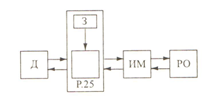
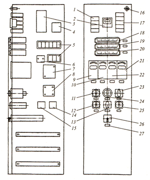
Rice. 123. Shield Shch-K2: 1.17 - two-lamp light panel TSB; 2 - ammeter; 3 - step-down transformer 0s0-0.25; 4 - rectifier 75GM8A2; 5 - automatic switches A-63; 6 - package switch PVZ-10; 7-block of switches PP1-10/K2; 8-network rectifier SV-4; 9 — fuel regulator UT; 10 - air regulator UT; 11 - boiler start switch; 12 - fan key; 13 - lock switch; 14 - outlet node; 15 - package switch node PV2-10; 16 - light signal lamp ASS-2; 18 - profile logometer L-64; 19 - membrane pressure gauge NPP-1; 20 — thrust gauge TNM-1; 21 — UT level regulator; 22 - vacuum regulator UT; 23 - switch for flame sensors KF 77/P-1US; 24 - switch for resistance thermometers PMT-4; 25 - key of the smoke exhauster KSVA; 26- fuel switch; 27 - frame for inscriptions