Who created the steam heating system. advantages and disadvantages compared to other coolants. classification of steam heating systems steam heating systems. Steam heating
If you heat water in an open vessel at atmospheric pressure, then its temperature will continuously increase until the entire mass of water warms up and boils. In the process of heating, the evaporation of water occurs from its open surface, when boiling, steam from water is formed on the heated surface and partially in the entire volume of the liquid. At the same time, the water temperature remains constant (equal to about 100 °C in the case under consideration), despite the continuous supply of heat to the vessel from outside. This phenomenon is explained by the fact that during boiling, the heat supplied is spent on the work of splitting water particles and forming steam from them.
Actions to save energy. Physical and structural-physical foundations Elements of life: water and air Pressure in liquids and gases Soundproofing Soundproofing Fire protection management. 4Construction installations Hazardous substances and their emission limit values Exhaust and flue gas systems. Furnace - air supply for combustion.
Liquid fuel: preparation - burner - boiler Preparation of fuel oil Connection of oil burners to one - and two-wire systems. Heating boilers for oil sprayers. Exhaust systems for petroleum fuels. Gas fuel: preparation - burner - boiler Gas preparation2 Gas burners3 Gas fireplaces4 Gas heating boilers5 Gas maintenance and repair.
When water is heated in a closed vessel, its temperature also rises only until the water boils. The steam released from the water accumulates in the upper part of the vessel above the surface of the water level; its temperature is equal to the temperature of boiling water. Such steam is called saturated.
If steam is not removed from the vessel, and the supply of heat to it (from outside) continues, then the pressure in the entire volume of the vessel will increase. As the pressure increases, so does the temperature of the boiling water and the steam formed from it. It has been experimentally established that each pressure has its own temperature of saturated steam and the boiling point of water equal to it, as well as its own specific volume of steam.
Photovoltaics4 Heat pumps Low energy CHP plants Fuel cell7 Low energy houses. Equipment for fixing heating and hot water systems1 Fixing equipment open systems heating and hot water supply Protective devices for closed systems heating and hot water supply.
Pumps and pressure dependencies in heating and hot water systems. Types of structural and structural properties of pumps Characteristics of pumps and pipelines Characteristics of power and pump power. Adapting the pump to the installation conditions. Equal and serial connection of pumps Pump in pump operation - causes and counteracts Pressure when water is heated in the pump Purge of the pump heating system. Hydraulic adjustment of the heating system.
So, at atmospheric pressure (0.1 MPa), water begins to boil and turns into steam at a temperature of about 100 ° C (more precisely, at 99.1 ° C); at a pressure of 0.2 MPa - at 120 °C; at a pressure of 0.5 MPa - at 151.1 ° C; at a pressure of 10 MPa - at 310 °C. From the above examples, it can be seen that with increasing pressure, the boiling point of water and its equal temperature of saturated steam increase. The specific volume of steam, on the contrary, decreases with increasing pressure.
13Water distribution system Water installation section. Space heaters and surface heating. 1 Room heaters Heated surfaces Heat meters and heat exchangers. 15Cleaning plants1 General messages2 Partitions3 Main components4 Heating medium5 Principle of operation6 Remote heating distribution Symbols used in heating installations. Advantages and disadvantages of remote heating installations.
Low steam heating Low steam heating Advantages and disadvantages of low steam heating Safety equipment and control of steam boilers low pressure Laying steam and condensate hoses. Steam pipe dehydration Ventilation and ventilation valve.
At a pressure of 22.5 MPa, the heated water passes into saturated steam instantly, so the latent heat of vaporization at this pressure is zero. A vapor pressure of 22.5 MPa is called critical.
If saturated steam is cooled, it will begin to condense, i.e. will turn into water; at the same time, it will give up its heat of vaporization to the cooling body. This phenomenon takes place in steam heating systems, in which saturated steam comes from a boiler room or a steam line. Here it is cooled by the air of the room, gives off its heat to the air, due to which the latter heats up, and the steam condenses.
Corrosion and how to prevent it Causes of corrosion of metallic materials. More explanations complex example water heater. Ventilation and air conditioning systems. Introduction and history of ventilation and air conditioning technologies. Department and tasks of ventilation and air conditioning. Controlled air exchange in living quarters. Components of the ventilation and air conditioning system.
Example of an air conditioning system Start-up only, acceptance test, measurement, regulation. Standardized rules for commissioning and construction work. General conditions of the contract for construction works General conditions of the contract for construction services General technical conditions for construction works.
The state of saturated steam is very unstable: even small changes in pressure and temperature lead to the condensation of part of the steam or, conversely, to the evaporation of water droplets present in saturated steam. Saturated steam, completely free of water droplets, is called dry saturated; Saturated steam with water droplets is called wet steam.
As a heat carrier in steam heating systems, saturated steam is used, the temperature of which corresponds to a certain pressure.
Steam heating systems are classified according to the following criteria:
According to the initial steam pressure - low pressure systems (p< 0,07 МПа);
Condensate return method - systems with gravity return (closed) and with condensate return using a feed pump (open);
Structural scheme of laying pipelines - systems with upper, lower and intermediate laying of distribution steam pipelines, as well as with laying of dry and wet condensate pipelines.
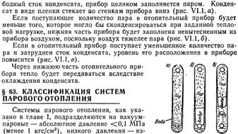
A diagram of a low-pressure steam heating system with an upper steam line is shown in fig. 1, a. The saturated steam generated in the boiler 1, passing through the dry steamer (separator) 12, enters the steam pipeline 5 and then enters the heating devices 7. Here, the steam gives off its heat through the walls of the devices to the air of the heated room and turns into condensate. The latter flows through the return condensate pipeline 10 into the boiler 1, while overcoming the steam pressure in the boiler due to the pressure of the condensate column, which is maintained at a height of 200 mm in relation to the water level in the dry steamer 12.
Figure 1. Low pressure steam heating system: a - scheme of the system with the upper laying of the steam pipeline; b - riser with lower steam wiring; 1 - boiler; 2 - hydraulic shutter; 3 - water gauge glass; 4 - air tube; 5 - supply steam pipeline; 6 - steam valve; 7 - heater; 8 - tee with a plug; 9 - dry condensate pipeline; 10 - wet condensate line; 11 - make-up pipeline; 12 - dry steamer; 13 - bypass loop
A tube 4 is mounted in the upper part of the return condensate pipeline 10, connecting it with the atmosphere for purge at the time of commissioning and decommissioning the system.
The water level in the steamer is controlled using a gauge glass 3. To prevent an increase in steam pressure in the system above a predetermined level, a hydraulic seal 2 is installed with a working liquid height equal to h.
The steam heating system is adjusted with steam valves 6 and control tees 8 with plugs, ensuring that when the steam boiler is operating in the design mode, each heater receives such an amount of steam that it would have time to completely condense in it. In this case, the release of steam from the previously opened control tee is practically not observed, and the probability of a "breakthrough" of condensate into the air tube 4 is negligible. Condensate losses in the steam heating system are compensated by feeding the boiler drum with specially treated water (freed from hardness salts) supplied through pipeline 11.
Steam heating systems, as already noted, come with upper and lower wiring of the steam pipeline. The disadvantage of the lower steam distribution (Fig. 1, b) is that the condensate formed in the lifting and vertical risers flows towards the steam and sometimes blocks the steam pipeline, causing hydraulic shocks. A calmer condensate drain occurs if the steam line 5 is laid with a slope towards the movement of steam, and the condensate line 9 is laid towards the boiler. To drain associated condensate from the steam pipeline into the condensate pipeline, the system is equipped with special bypass loops 13.
If the steam heating network has a large branching, then the gravity discharge of condensate is carried out into a special collection tank 3 (Fig. 2), from where it is pumped by pump 8 to boiler 1. The pump operates periodically, depending on the change in the water level in the dry steamer 2. Such a heating scheme called open; in it, to separate condensate from steam, as a rule, steam traps (condensate pots) are used 7. The latter most often have a float or bellows design (Fig. 3).
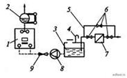
Figure 2. Scheme of forced condensate return: 1 - boiler; 2 - dry steamer; 3 - condensate tank; 4 - air tube; 5 - bypass line; 6 - steam valves; 7 - steam trap; 8 - make-up pump; 9 - check valve
The float steam trap (see Fig. 3, b) works like this. Steam and condensate through the inlet enter under the float 3, which is connected by a lever to the ball valve 4. The float 3 has the shape of a cap. Under steam pressure, it floats, closing the ball valve 4. The condensate fills the entire chamber of the steam trap; in this case, the steam under the valve condenses and the float sinks, opening the ball valve. The condensate is discharged in the direction indicated by the arrow until new portions of steam accumulated under the hood cause the hood to float. Then the steam trap cycle is repeated.
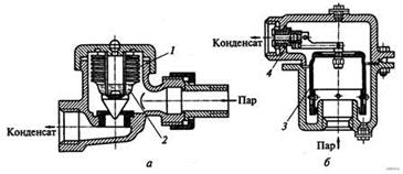
Figure 3. Steam traps: a - bellows; b - float; 1 - bellows; 2 - low-boiling liquid; 3 - float (overturned cap); four - ball valve
On the industrial enterprises having industrial consumers of high-pressure steam, steam heating systems are connected to heating mains according to the schemes high pressure(Fig. 4). Steam from a private or regional boiler house enters the distribution manifold 1, where its pressure is controlled by a pressure gauge 3. Then, through the steam pipelines leaving the comb 1, 2 steam is sent to industrial consumers, and through the T1 steam pipelines to consumers of the steam heating system. Steam pipelines T1 are connected to comb 6 of steam heating, and comb 6 to comb 1 through pressure reducing valve 4. The pressure reducing valve throttles steam to a pressure of not more than 0.3 MPa. The wiring of high-pressure steam pipelines of steam heating systems is usually carried out from above. Diameters of steam pipelines and heating surfaces heating appliances these systems are somewhat smaller than those of low-pressure steam heating systems.

Figure 4. Scheme of high pressure steam heating: 1 - distribution comb; 2 - steam pipeline; 3 - manometer; 4 - pressure reducing valve; 5 - bypass (bypass line); 6 - comb of the heating system; 7 - cargo safety valve; 8 - fixed support; 9 - compensators; 10 - steam valves; 11 - condensate pipeline; 12 - steam traps
The disadvantage of steam heating systems is the difficulty in regulating the heat output of heating devices, which ultimately leads to excessive fuel consumption during the heating season.
The diameters of the pipelines of steam heating systems are calculated separately for steam and condensate pipelines. The diameters of low-pressure steam pipelines are determined in the same way as in water heating systems. The pressure loss in the main circulation ring of the system? p pk, Pa, is the sum of the resistances (pressure losses) of all sections included in this ring:
where n is the fraction of pressure loss due to friction from the total losses in the ring; ?I is the total length of sections of the main circulation ring, m.
Then the required steam pressure in the boiler pk is determined, which should ensure that pressure losses in the main circulation ring are overcome. In low-pressure steam heating systems, the difference in steam pressure in the boiler and in front of the heating devices is spent only to overcome the resistance of the steam line, and the condensate returns by gravity. To overcome the resistance of heating devices, a pressure reserve p pr \u003d 2000 Pa is provided. The specific vapor pressure loss can be determined by the formula
| | (3) |
where 0.9 is the value of the coefficient that takes into account the pressure margin to overcome unaccounted resistances.
For low-pressure steam heating systems, the fraction of friction losses n is taken to be 0.65, and for high-pressure systems - 0.8. The value of the specific pressure loss calculated by formula (3) must be equal to or slightly greater than the value determined by formula (2).
The diameters of the steam pipelines are determined taking into account the calculated specific pressure losses and heat load of each calculated section.
Steam pipeline diameters can also be determined using special tables in reference books or a nomogram (Fig. 5) compiled for average low pressure steam densities. When designing steam heating systems, the steam velocity in steam pipelines should be taken taking into account the recommendations given in Table. one.
Otherwise, the methodology hydraulic calculation low pressure steam pipelines and circulation ring resistances is completely analogous to the calculation of pipelines leading CLASSIFICATION OF STEAM HEATING SYSTEMS
| Steam heating systems, as indicated in chapter I, are divided into vacuum-steam-absolute pressure<0,1 МПа (менее 1 кгс/см2), низкого давления - избыточное давление 0,005-0,07 МПа (0,05- 0,7 кгс/см2) и высокого давления - избыточное давление >0.07 MPa (more than 0.7 kgf/cm2). Steam systems low pressure, in turn, are divided into open, communicating with the atmosphere, and closed, not communicating with the atmosphere. According to the method of returning condensate to the boiler, the systems are closed - with a direct return of condensate to the boiler and open - with the return of condensate to the condensate tank and its subsequent pumping from the tank to the boiler. According to the connection scheme of pipes with devices, systems can be two-pipe and one-pipe (both with upper, lower and middle piping, with dry and wet condensate pipelines), with associated steam and condensate flow and dead-end. Dry pipelines are called condensate pipelines, the sections of which are not completely filled with condensate, and during interruptions in the operation of the system are not filled with water. Wet pipelines are called condensate pipelines, which are always filled with water. |
heating systems
Steam heating systems use the property of steam during condensation to release the latent heat of phase transformation. When condensing 1 kg of steam in a heating device, the room receives about 2260 kJ of heat.
Compared to hot water heating systems, steam heating systems have the following advantages:
1) due to the low density of steam, it moves with large
speeds, as a result of which smaller diameters of heat pipes are required than with water heating, therefore the cost of heat pipes in steam heating systems is lower than in water heating systems;
2) a greater heat transfer coefficient from steam to the walls of the heating device (due to the high value of the latent heat of phase transformation), due to this and high temperature steam the surface area of heaters in steam heating systems is approximately 25-30% less than in water heating systems;
3) rapid heating of the premises and shutdown of the system from work;
4) the possibility of using heating systems in high-rise buildings due to low steam density.
However, along with all the listed positive properties, steam has a number of significant disadvantages:
1) the impossibility of central quality regulation (changes in the temperature of the coolant) of the supply of heat, as a result of which it is difficult to maintain a constant and uniform temperature in the room; ensuring a constant temperature is achieved by periodically turning off the system (regulation by "passes"), which is inconvenient in operation;
2) air pollution by products of dry sublimation (decomposition) of organic dust deposited on the surface of heating appliances;
3) large heat losses of steam pipelines;
4) reduction in the service life of steam pipelines as a result of air entering the system during its periodic shutdown, which causes corrosion intensification, especially of condensate pipelines.
The disadvantages of steam as a heat carrier do not allow using it for heating residential buildings, hostels, children's and medical institutions, libraries, museums and a number of others.
In accordance with SNiP 2.04.05-86, it is recommended to install steam heating systems in industrial premises (according to mandatory appendix 10), as well as in stairwells, pedestrian crossings, lobbies and heating points.
Classification, diagrams and equipment of steam heating systems
Steam heating systems are divided into:
Due to the presence of connection with the atmosphere,
According to the value of the initial steam pressure,
The method of returning condensate to the boiler or heating network,
The location of the steam pipeline and the layout of the risers.
Currently, open (communicating with the atmosphere) heating systems are used.
According to the pressure supplied to the heating system, heating systems are distinguished:
High (pex >0.07 MPa),
Low (r izb<0,07 МПа) давления;
Vacuum steam (r abs<0,1 МПа).
Vacuum steam systems are not used in our country.
According to the method of condensate return, steam heating systems are divided into:
Closed (due to the slope of the pipelines, condensate returns by gravity from the heaters to the boiler or to the heating network);
Open (condensate first enters the condenser tank, and then pumped to the boiler or to the heating network).
According to the location of the steam pipeline and the scheme of risers, steam heating systems can be performed in the same way as water heating systems, i.e., with upper, lower and intermediate steam distribution with one-pipe and two-pipe heating service schemes.
On fig. 9.1 shows a diagram of a closed low pressure steam heating system with overhead steam distribution. Steam from the boiler through the main riser 1, due to the pressure difference in the boiler and in the heating devices, it rises into the main steam pipeline 2 and further along the steam risers 3 and branches 4, equipped with valves, reaches the heating appliances. Here, the steam condenses, releasing the latent heat of vaporization into the heated room through the walls of the appliances. The resulting condensate through the condensate risers 5 and the collection condensate pipeline b, laid with a slope (not less than 0.005) in the direction of its movement, returns by gravity to the boiler, which is significantly lower than the heaters, so that the condensate column h balances the steam pressure in the boiler. For example, at a steam pressure in the boiler pg = 0.02 MPa, the condensate column h must be at least 2 m.
For normal removal of air from the system, the diameter of the condensate pipeline in the scheme under consideration must be such that the flowing condensate fills no more than half the diameter of the pipe. Compliance with this condition allows the air space of the condensate pipeline to communicate with the atmosphere using pipe 7 9. The place of connection of pipe 7 to the condensate pipeline must be above the water level //-// (see Fig. 9.1) by at least 250 mm; stop valves are not installed on it. Under this condition, the main condensate pipeline will never be completely filled with water. Such systems are called steam heating systems with a "dry" condensate line.
With a large length of the steam pipeline in closed systems, to reduce the depth of the boiler rooms, the condensate pipeline is laid below the water level in the boiler. Such a condensate pipeline is called “wet”, since it is completely filled with condensate. Air is removed from the heating system with a “wet” condensate line through a special air network of pipes with a diameter of 15-20 mm, connected to condensate risers 250 mm above the possible level of condensate in them.

Fig.9.1. Scheme of steam heating with upper steam distribution.
Fig.9.2. Steam heating system with bottom steam distribution.
A low-pressure steam heating system with lower steam distribution differs from a system with upper distribution mainly in the location of the main steam pipeline, in which a special hydraulic seal is installed or a water trap is installed at the far riser to drain condensate from the risers and the main steam pipeline (Fig. 9.2).
Open-loop steam heating systems (Fig. 9.3) are used at a steam pressure of Rg = 30 kPa and above. In contrast to a closed system, the condensate in it does not flow into the boiler 1, but into the condensate tank 3, from where the pump 2, switched on automatically or manually, is fed into the boiler. In these steam heating systems, the heaters can be positioned at any height relative to the boiler.
A horizontal single-pipe flow system is used, which is economical and quite acceptable for heating large premises of buildings of 1-2 floors, in which individual adjustment of the heat transfer of devices is not required. High-pressure steam heating Р abs > 0.17 MPa is usually taken in cases where steam is produced in factory boilers and its main consumer is production.
Consider the control unit and high pressure steam heating circuit with upper steam distribution (Fig. 9.4). Steam from the boiler room enters the control unit with a pressure of Psb=0.6 MPa, which is necessary for production. A steam distribution manifold is installed for steam distribution 2 with two branches.
Since for the heating system of a building, steam can be used with pressure R izb not higher than 0.3 MPa, then to reduce the pressure from 0.6 to 0.3 MPa, a pressure reducing valve is installed in front of the second steam distribution manifold 3 bypass line 4 (in case of repair). After the pressure reducing valve, a safety valve of lever type 5 is installed, adjusted to p;! 3 b \u003d 0.3 MPa. Pressure gauges are available to monitor the pressure on the tori 1. From the second steam distribution manifold, steam flows through the main risers and steam pipelines 6 and heating risers 7 into heating devices. Valves 9 are installed at the devices on the steam and condensate lines; they are necessary in order to reduce the passage of steam into the condensate line and turn off the devices. In a high-pressure steam heating system, significant thermal elongations of pipelines occur (up to 1.5-2 mm per 1 m). To compensate for elongations, pipeline turns are used and compensators are installed on straight main pipelines. 8.
High-pressure steam heating systems are used only open-circuited. To prevent the breakthrough of steam from heating appliances, steam traps are installed in the condensate pipeline and the condensate tank. 10 or retaining washers that allow condensate to pass through and retain steam.

![]() Fig.9.3. Scheme of a horizontal single-pipe flow open low-pressure steam heating system with condensate pumping.
Fig.9.3. Scheme of a horizontal single-pipe flow open low-pressure steam heating system with condensate pumping.
1 - boiler, 2 - condensate pump, 3 - condensate tank
Fig.9.4 Scheme of high pressure steam heating system with upper steam distribution.