
What are the functions of the alternator in the car? Automobile generator: types, device, principle of operation and features of the device
The battery powers the car's on-board network only in the parking lot and at the time of starting the engine. Then the baton is picked up by the unit, which converts the mechanical work of the rotating crankshaft into electricity. Without this powerful power source, the normal operation of the vehicle is impossible, since the battery charge is not infinite. Motorists engaged in self-maintenance of their car should study the principle of operation of a car generator and its characteristic malfunctions.
How is a generator set up?
The main part of the device is a body consisting of two covers and made of aluminum alloy, which ensures efficient removal of excess heat. A mounting flange or a tide with a through hole for a long bolt is provided on the body (depending on the brand of car). In general, the unit device looks like this:
- The front and rear housing covers are tightened together with screws, and a fixed stator winding is attached to them from the inside.
- Holes are made at the ends of the covers, where the bearings of the rotor shaft are pressed in. There are also ventilation openings on the sides that serve to cool the insides of the generator.
- The rotor rotating inside the housing on bearings is a shaft with a second winding and two metal bushings with wedge-shaped cutouts. From the side of the front cover, a drive pulley is screwed to the shaft with a nut.
- Outside the back cover there are copper slip rings and graphite brushes inserted into special sockets - brush holders. Nearby, on a plate in the form of a horseshoe, a rectifier circuit on diodes (otherwise, a diode bridge) is assembled.
- The elements of current transfer from the rotor (brushes, rings) and the diode circuit are closed from the outside by a protective casing with numerous holes for cooling. An impeller is fixed at the rear end of the shaft (under the casing), which drives air through the unit housing.
The device of the electric current generator has changed little since its invention. This unit, designed to convert rotational energy into electricity, features a perfect design and high efficiency. The efficiency of the device is 98-99%.
 Since current-carrying sliding contacts (brushes) are a weak link in the design and wear out quickly, more modern generators have implemented a brushless method of current transmission. The process involves an asterisk mounted on the shaft and an additional winding attached from the inside to the end of the back cover.
Despite the apparent complexity of the design of a car electric generator, disassembling it is quite simple. To pull out the rotor, it is enough to unscrew the casing and the screws that tighten the 2 covers, having previously removed the drive pulley.
Location and connection diagram of the unit
The generator rotor shaft is driven by a belt drive connecting it to the crankshaft pulley. Therefore, the unit is always located near the front end of the engine, where the timing gear is located. In front-wheel drive vehicles, the engine is rotated 90° and the generator is on the right side (when viewed in the direction of travel).
Note. In passenger cars, the device is often placed in the lower zone, above the protective covers. SUV manufacturers are trying to raise the generator higher so that water does not get inside while overcoming deep puddles and fords.
The stator winding of the apparatus is three-phase, as it consists of 3 separate sections rotated relative to each other by 120°. Therefore, the windings are connected in a "star", and a pair of diodes is connected to the output of each phase, converting alternating current to direct current. In total, the rectifier bridge includes 3 pairs of elements (6 diodes).
The connection diagram of a car generator consists of the following elements:
- built-in diode rectifier, described above;
- relay - automatic output voltage regulator;
- a group of additional diodes (3 pcs.) Rectifying the current for the regulator;
- lamp - battery charging indicator;
- egnition lock;
- battery.
The outputs of the rotor and stator windings are connected to the relay-regulator (through a rectifier bridge). The task of this block is to regulate the power at the output of the generator unit, keeping the voltage in the range of 13.8–14.7 volts.
 The circuit of the electric generator and the relay includes the contacts of the ignition switch and the battery, which receives a charge during the operation of the engine. From the line leading to the regulator unit, a light on the dashboard is powered, indicating that the on-board network is powered from the battery. When the motor starts and current generation begins, the indicator goes out.
Details about the algorithm of work
The principle of operation of the generator is based on a simple physical phenomenon called electromagnetic induction. The bottom line is this: if you put a magnetic field on a multi-turn winding of copper wire that changes direction with a certain frequency, then an alternating current of the same frequency will appear at the output of the coil. It remains only to create the mentioned field around the stator windings that generate voltage.
In practice, the generation of electricity occurs according to the following algorithm:
- The source of the alternating magnetic field of an automobile electric generator is a self-excitation winding located in the rotor. To initially magnetize the wedge-shaped bushings, a pulse is applied to it low power from the battery.
- After starting the motor and reaching a certain speed of the crankshaft, the stator windings give out an alternating current, rectified by power diodes. From this point on, the rotor winding is powered by the generator itself, that is, self-excitation occurs. An external power supply is no longer required.
- Direct current from the diode bridge is sent to the relay-regulator unit. Since the voltage value “jumps” along with, the task of electronics is to stabilize the drops in the range from 13.8 to 14.7 V.
- Further, the voltage is supplied to recharge the battery and to the on-board electrical network of the car.
The voltage regulator relay can be part of the generator set or used as a separate unit.
The current in the stator windings arises as a result of the rotation of the alternating magnetic field created by the rotor coil. The faster the shaft spins, the higher the output voltage and frequency. The conversion to direct current is provided by semiconductors (diodes) mounted on a heat sink plate and blown by a fan impeller.
 The brushless type generator arrangement allows the stator winding to be energized without an external power source. The magnetization of steel bushings starts at low shaft speeds due to the special design of the rotor and an additional coil. Therefore, when you drive a car with a dead battery, the crankshaft turns enough to turn the generator on.
Common faults
The indicator of the generator set's operability is a red signal lamp located on the instrument panel. Its inclusion indicates that instead of the generator, the on-board network provides energy to the battery, which is gradually discharged.
Reference. If you continue to drive with the light on, the battery charge will not last for a long time. A large amount of energy takes away sparking on spark plugs and power electronic systems engine control.
A car electric generator is a fairly reliable unit, but not eternal. As a result of the wear of parts, the motorist has to deal with the following malfunctions:
- stretching and slipping of the drive belt (the signal lamp may blink);
- abrasion of the working surface of brushes or slip rings;
- wear and destruction of bearing cages;
- failure of the electronics of the relay-regulator;
- violation of the integrity of electrical circuits.
The last 2 reasons lead to a complete failure of the generator - a breakdown of the regulator and an open circuit. Then the voltage from the unit does not come at all. In other cases, battery charging continues, but intermittently. With worn rotor bearings, the operation of the car's generator is accompanied by a lot of noise, and the slipping belt makes a loud squeak.
Replacing or tensioning the drive belt is not a serious problem; the generator does not need to be dismantled. In most vehicles, the tensioner bracket fixing nut and the assembly mounting bolt are loosened, after which the belt can be dropped or tensioned. In some machines, the belt drive is adjusted by a separate roller.
To replace bearings, brushes or rings, the generator will have to be removed and disassembled. It is better to dismantle before buying new parts, so as not to make a mistake with the dimensions.
 For troubleshooting electrical circuits and blocks, you should contact the masters of the service station.
Some breakdowns, which are quite rare, lead to a complete replacement of the generator:
- short circuit of the turns of the rotor or stator winding;
- breakage inside the coil;
- wear of the shaft or socket in the cover, as a result of which the bearing race slips.
The performance of the generator can be checked in garage conditions by connecting a voltmeter to the battery terminals. The measurement is made at idle speed of the engine. If the voltage exceeds 14.7 V, there is a so-called overcharging and the problem lies in the regulator block. Readings below 13.6 volts indicate little or no current generation.
The cause of the problem is also a breakdown of the diodes of the rectifier bridge, which changes entirely, along with the "horseshoe". If dirt and oil from the engine constantly get on the heating diodes (through the ventilation openings of the casing), then the back of the generator may ignite. After detecting grease inside the unit, it must be disassembled and thoroughly cleaned.
When it comes to powering a car with electrical energy, many car owners, for some reason, only remember the battery (battery), here, we read - how to choose a battery. But after all, the main part, due to which the transformation of the energy coming from the engine, from mechanical to electrical, is the generator. It is he who feeds all the electrical equipment in the car (when running) and charges the battery.
The device of the automobile generator.
Consider what it consists of, as well as how this automotive unit works. True, I will immediately make a reservation that we will be talking about a car alternator, since it is this type of them that is installed on modern vehicles.
What is a generator made of?

car alternator usually has the following components:
- a pulley is a kind of entry point (using a belt) for mechanical energy into the generator;
- the body of the generator, which is formed by two covers, front and rear, almost all other components of the part we are considering are actually attached to them;
- rotor - is attached to the front cover of the generator housing and consists of a steel shaft with 2 steel bushings (they are beak-shaped) and an excitation winding between them, to which, as a rule, copper cylindrical slip rings are attached;
- stator - is responsible for the power of the generator and consists of a metal core with 36 grooves and a winding;
- rectifier shield - with the help of 6 powerful diodes (3 positive and 3 negative) it converts the voltage that the stator creates into the DC voltage of the car's on-board network;
- voltage regulator - monitors that, i.e. regulates that the voltage of the on-board network of the machine is always within the specified limits, regardless of the load, temperature environment and rotor performance.
Diagram of a car generator.

The principle of operation of the generator.
This means that when the driver turns the key in the ignition, voltage is supplied to the winding (there is a magnetic field in it) in the rotor from the battery through the brush assembly. And as soon as the engine crankshaft starts to rotate, as you remember, thanks to the pulley, the generator rotor also starts to rotate. The magnetic field that is created in the latter starts the stator windings, thereby creating an alternating voltage at their terminals. At a certain speed, the generator stops being powered by mechanical energy and begins to create the voltage it needs on its own (the excitation winding is powered inside the generator).
The resulting voltage is sent to the rectifier board, where it is converted into direct current, which charges the battery and powers the car's electrical appliances.
Moreover, if the crankshaft changes its speed of rotation, then a voltage regulator is also included in this system. Depending on the external load, it regulates the turn-on time of the field winding: with a decrease in load and / or an increase in the speed of rotation of the crankshaft, the turn-on time of the field winding is reduced, and with an increase in load and / or a decrease in crankshaft speed, it increases. That is the job of a car generator. In addition, I recommend that you read two articles:
The most basic generator function – battery charge battery and power electrical equipment engine.
Therefore, let's take a closer look generator circuit how to connect it correctly, and also give some tips on how to check it yourself.
Generator A mechanism that converts mechanical energy into electrical energy. The generator has a shaft on which a pulley is mounted, through which it receives rotation from the engine crankshaft.
A car generator is used to power electrical consumers, such as: an ignition system, an on-board computer, automotive lighting, a diagnostic system, and it is also possible to charge car battery. The power of a passenger car generator is approximately 1 kW. Automotive generators are quite reliable in operation, because they ensure the uninterrupted operation of many devices in the car, and therefore the requirements for them are appropriate.
Generator device
The device of a car generator implies the presence of its own rectifier and control circuit. The generating part of the generator, using a fixed winding (stator), generates a three-phase alternating current, which is then rectified by a series of six large diodes and the direct current charges the battery. Alternating current is induced by the rotating magnetic field of the winding (around the field winding or rotor). Further, the current through the brushes and slip rings is fed to the electronic circuit.

Generator device: 1. Nut. 2. Washer. 3.Pulley. 4. Front cover. 5. Distance ring. 6. Rotor. 7. Stator. 8.Rear cover. 9. Casing. 10. Gasket. 11. Protective sleeve. 12. Rectifier unit with capacitor. 13.Schelkoderzhatel with a voltage regulator.
The generator is located in front of the car engine and is started using the crankshaft. The connection diagram and the principle of operation of the car generator are the same for any car. Of course, there are some differences, but they are usually associated with the quality of the manufactured goods, the power and layout of the components in the motor. In all modern cars, alternating current generator sets are installed, which include not only the generator itself, but also a voltage regulator. The regulator equally distributes the current strength in the field winding, it is due to this that the power of the generator set itself fluctuates at the moment when the voltage at the output power terminals remains unchanged.
New cars are most often equipped with an electronic unit on the voltage regulator, so the on-board computer can control the amount of load on the generator set. In turn, on hybrid vehicles, the generator performs the work of a starter-generator, a similar scheme is used in other designs of the stop-start system.
The principle of operation of the auto generator

Connection diagram of the generator VAZ 2110-2115
Generator connection diagram alternating current includes the following components:
- Battery.
- Generator.
- Fuse block.
- Ignition.
- Dashboard.
- Rectifier block and additional diodes.
The principle of operation is quite simple, when the ignition is turned on, plus through the lock, the ignition goes through the fuse box, light bulb, diode bridge and goes through the resistor to minus. When the light on the dashboard lights up, then the plus goes to the generator (to the field winding), then in the process of starting the engine, the pulley starts to rotate, the armature also rotates, due to electromagnetic induction, an electromotive force is generated and alternating current appears.
The most dangerous for the generator is the closure of the heat sink plates connected to the “mass” and the “+” terminal of the generator with metal objects accidentally caught between them or conductive bridges formed by pollution.
Further, the diode passes plus into the rectifier unit through the sinusoid into the left shoulder, and minus into the right shoulder. Additional diodes on the light bulb cut off the minuses and only pluses are obtained, then it goes to the dashboard node, and the diode that is there it passes only the minus, as a result, the light goes out and the plus then goes through the resistor and goes to minus.

The principle of operation of a DC car generator can be explained as follows: a small DC current begins to flow through the excitation winding, which is regulated by the control unit and maintained at a level of just over 14 V. Most generators in a car are capable of producing at least 45 amperes. The alternator is running at 3000 rpm and above - if you look at the ratio of the fan belts to the pulleys, it will be two or three to one in relation to the engine frequency.
To avoid this, the plates and other parts of the generator rectifier are partially or completely covered with an insulating layer. In a monolithic design of the rectifier unit, heat sinks are mainly combined with mounting plates made of insulating material, reinforced with connecting bars.
Wiring diagram for a generator on a VAZ 2107
The VAZ 2107 charging scheme depends on the type of generator used. To recharge the battery on cars such as: VAZ-2107, VAZ-2104, VAZ-2105, which are on a carburetor engine, you will need a G-222 type generator or its equivalent with a maximum output current of 55A. In turn, VAZ-2107 cars with an injection engine use a generator 5142.3771 or its prototype, which is called an increased energy generator, with a maximum output current of 80-90A. You can also install more powerful generators with a return current of up to 100A. Rectifier units and voltage regulators are built into absolutely all types of alternators; they are usually made in one housing with brushes or removable and mounted on the housing itself.
The VAZ 2107 charging scheme has slight differences depending on the year of manufacture of the car. The most important difference is the presence or absence of a charge control lamp, which is located on the instrument panel, as well as the way it is connected and the presence or absence of a voltmeter. Such schemes are mainly used on carbureted cars, while the scheme does not change on cars with injection engines, it is identical to those cars that were previously manufactured.
Generator set designations:
- “Plus” of the power rectifier: “+”, V, 30, V+, BAT.
- “Ground”: “-”, D-, 31, B-, M, E, GRD.
- Field winding output: W, 67, DF, F, EXC, E, FLD.
- Conclusion for connection with a lamp of serviceability control: D, D+, 61, L, WL, IND.
- Phase output: ~, W, R, STA.
- Output of the zero point of the stator winding: 0, MP.
- The output of the voltage regulator for connecting it to the on-board network, usually to the “+” battery: B, 15, S.
- The output of the voltage regulator to power it from the ignition switch: IG.
- The output of the voltage regulator for connecting it to the on-board computer: FR, F.

Scheme generator VAZ-2107 type 37.3701
- Accumulator battery.
- Generator.
- Voltage regulator.
- Mounting block.
- Ignition switch.
- Voltmeter.
- Control lamp of a charge of the rechargeable battery.
When the ignition is turned on, the plus from the lock goes to fuse No. 10, and then it goes to the battery charge control lamp relay, then it goes to the contact and to the coil output. The second output of the coil interacts with the central output of the starter, where all three windings are connected. If the relay contacts are closed, then the control lamp is on. When the engine is started, the generator generates current and an alternating voltage of 7V appears on the windings. A current flows through the relay coil and the armature begins to attract, while the contacts open. Generator No. 15 passes current through fuse No. 9. Similarly, the excitation winding receives power through the brush voltage generator.
VAZ charging scheme with injection engines
Such a scheme is identical to the schemes on other VAZ models. It differs from the previous ones in the way of excitation and control for the serviceability of the generator. It can be carried out using a special control lamp and a voltmeter on the instrument panel. Also, through the charge lamp, the initial excitation of the generator occurs at the time of the start of work. During operation, the generator operates “anonymously”, that is, excitation comes directly from the 30th output. When the ignition is turned on, power through fuse No. 10 goes to the charging lamp in the instrument panel. Then, through the mounting block, it enters the 61st output. Three additional diodes provide power to the voltage regulator, which in turn transmits it to the excitation winding of the generator. In this case, the control lamp will light up. It is at the very moment when the generator will work on the plates of the rectifier bridge that the voltage will be much higher than that of the battery. In this case, the control lamp will not burn, because the voltage on its side on the additional diodes will be lower than on the side of the stator winding and the diodes will close. If during the operation of the generator the control lamp lights up to the floor, this may mean that additional diodes are broken.
Checking the operation of the generator
You can use certain methods in several ways, for example: you can check the recoil current of the generator, the voltage drop on the wire that connects the current output of the generator to the battery, or check the regulated voltage.
To check, you will need a multimeter, a car battery and a lamp with soldered wires, wires for connecting between the generator and the battery, and you can also take a drill with a suitable head, as you may have to turn the rotor by the nut on the pulley.
Elementary test with a light bulb and a multimeter
Wiring diagram: output terminal (B+) and rotor (D+). The lamp must be connected between the main generator output B + and the D + contact. After that, we take the power wires and connect the “minus” to the negative terminal of the battery and to the generator ground, “plus”, respectively, to the plus of the generator and to the B + output of the generator. We fix on a vise and connect.
"Mass" must be connected to the last very, so as not to short-circuit the battery.
We turn on the tester in the (DC) direct current mode, we hook one probe to the battery to the “plus”, the second also, but to the “minus”. Further, if everything is in working order, then the light should light up, the voltage in this case will be 12.4V. Then we take a drill and begin to turn the generator, respectively, the light at this moment will stop burning, and the voltage will already be 14.9V. Then we add a load, take an H4 hologen lamp and hang it on the battery terminal, it should light up. Then, in the same order, we connect the drill and the voltage on the voltmeter will already show 13.9V. In passive mode, the battery under the light bulb gives 12.2V, and when we turn the drill, then 13.9V.

Generator test circuit
- Check the generator for operability by short circuit, that is, “for a spark”.
- It is also undesirable to allow the generator to work without consumers turned on, while operation with the battery disconnected is undesirable.
- Connect terminal “30” (in some cases B+) to ground or terminal “67” (in some cases D+).
- Carry out welding work on the car body with the wires of the generator and battery connected.
The generator is the main source of electricity for the machine. We will tell you in detail how it works, what its device inside consists of. The information is suitable for beginners and experienced motorists.
How does it work
When starting a car engine, the main consumer of electricity is the starter, the current reaches hundreds of amperes, which causes a significant drop in battery voltage. In this mode, consumers are powered only by the battery, which is intensively discharged. Immediately after starting the engine, the generator becomes the main source of electricity.The car generator is a source of constant recharging of the battery while the engine is running. If it does not work, the battery will quickly run out. It provides the required current to charge the battery and operate electrical appliances. After recharging the battery, the generator reduces the charging current and operates normally.
When powerful consumers are turned on (for example, a rear window defroster, headlights) and low engine speeds, the total current consumed may be greater than the generator is capable of delivering. In this case, the load will fall on the battery and it will begin to discharge.
Drive and mount
The drive is carried out from the crankshaft pulley by a belt drive. The larger the pulley diameter on the crankshaft and the smaller the pulley diameter, the higher the generator speed, respectively, it is able to deliver more current to consumers.On modern machines, the drive is carried out by a V-ribbed belt. Due to its greater flexibility, it allows the generator to be fitted with a small diameter pulley and thus obtain high gear ratios. V-ribbed belt tension carried out by tension rollers with a stationary generator.
The device and what it consists of
Any car generator contains a stator with a winding, sandwiched between two covers - the front, on the drive side, and the rear, on the side of the slip rings. Generators are bolted to the front of the engine on special brackets. Mounting feet and tension eye are located on the covers.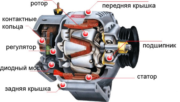 The covers, cast from aluminum alloys, have ventilation windows through which air is blown by a fan. Traditional design generators are equipped with ventilation windows only in the end part, and "compact" design - on the cylindrical part above the front sides of the stator winding.
 On the cover from the side of the slip rings, a brush assembly is attached, which is combined with a voltage regulator, and a rectifier assembly. The covers are usually pulled together by three or four screws, and the stator is sandwiched between the covers, the seating surfaces of which cover the stator along the outer surface.
 Generator stator: 1 - core, 2 - winding, 3 - grooved wedge, 4 - groove, 5 - output for connection with a rectifier
The stator is made of steel sheets with a thickness of 0.8 ... 1 mm, but more often it is wound "on edge". When the stator package is made by winding, the stator yoke usually has protrusions above the grooves, along which the position of the layers relative to each other is fixed during winding. These projections improve the cooling of the stator due to the more developed outer surface.
The need to save metal led to the creation of the design of the stator package, recruited from separate horseshoe-shaped segments. The fastening between the individual sheets of the stator package into a monolithic structure is carried out by welding or rivets. Almost all mass-produced car generators have 36 slots in which the stator winding is located. The grooves are insulated with film insulation or sprayed with epoxy compound.
 Automotive Alternator Rotor: a - assembled; b - disassembled pole system; 1.3-pole halves; 2 - excitation winding; 4 - contact rings; 5 - shaft
A feature of automotive generators is the type of rotor pole system. It contains two pole halves with protrusions - beak-shaped poles, six on each half. The pole halves are stamped and may have projections. In the absence of protrusions, when pressing onto the shaft, a bushing with an excitation winding wound on the frame is installed between the pole halves, while winding is carried out after the bushing is installed inside the frame.
Rotor shafts are made of mild free-cutting steel. But when using a roller bearing, the rollers of which run directly along the end of the shaft from the side of the slip rings, the shaft is made of alloy steel, and the shaft pin is hardened. At the threaded end of the shaft, a groove is cut for the key for attaching the pulley.
In many modern designs, the key is missing. In this case, the end part of the shaft has a recess or a turnkey protrusion in the form of a hexagon. This allows you to keep the shaft from turning when tightening the pulley mounting nut, or when disassembling the generator, when you need to remove the pulley and fan.
brush knot- this is a structure in which brushes are placed i.e. sliding contacts. Two types of brushes are used in automotive alternators - copper graphite and electrographite. The latter have an increased voltage drop in contact with the ring compared to copper-graphite ones. They provide significantly less wear on the slip rings. The brushes are pressed against the rings by the force of the springs.
 Rectifier nodes two types are used. These are either heat sink plates into which the diodes of the power rectifier are pressed, or structures with highly developed fins and the diodes are soldered to the heat sinks. The diodes of the additional rectifier usually have a plastic case of a cylindrical shape or in the form of a pea, or they are made in the form of a separate sealed unit, the inclusion in the circuit of which is carried out by busbars.
The most dangerous is the closure of the heat sink plates connected to the "mass" and the "+" terminal of the generator with metal objects accidentally caught between them or conductive bridges formed by pollution, tk. this causes a short circuit in the battery circuit and a fire is possible. To avoid this, the plates and other parts of the generator rectifier are partially or completely covered with an insulating layer. In a monolithic design of the rectifier unit, heat sinks are mainly combined with mounting plates made of insulating material, reinforced with connecting bars.
Bearing units of generators these are typically deep groove ball bearings with one-time grease lubrication for life and single or double-sided seals built into the bearing. Roller bearings are used only on the side of the slip rings and quite rarely, mainly by American companies. The fit of ball bearings on the shaft from the side of the slip rings is usually tight, from the drive side - sliding, in the seat of the cover, on the contrary - from the side of the slip rings - sliding, from the drive side - tight.
The auto generator is cooled by one or two fans mounted on its shaft. At the same time, in the traditional design of generators, air is sucked in by a centrifugal fan into the cover from the side of the slip rings. For generators with a brush assembly, a voltage regulator and a rectifier outside the internal cavity and protected by a casing, air is sucked in through the slots in this casing, directing air to the hottest places - to the rectifier and voltage regulator. 
Cooling system: a - devices of conventional design; b - for elevated temperature in the engine compartment; c - compact design devices. Arrows show the direction of air flow
On cars with a dense layout of the engine compartment, generators with a special casing are used, through which cold outside air enters it. For "compact" generators, cooling air is taken from both the rear and front covers.
What is a voltage regulator for?
 Regulators maintain the generator voltage within certain limits for optimal operation of electrical appliances included in the vehicle's on-board network. Generators are equipped with semiconductor electronic voltage regulators built into the housing. Schemes of their execution and design may vary, but the principle of operation is the same.
 Voltage regulators have the property of thermal compensation - changing the voltage supplied to the battery, depending on the air temperature in the engine compartment for optimal battery charging. The lower the air temperature, the more voltage must be supplied to the battery and vice versa. The value of thermal compensation reaches up to 0.01 V per 1°C. Some models of remote regulators have manual voltage level switches (winter/summer).
The principle of operation of a car generator is not at all difficult to understand if we consider the main components of this important vehicle device, which converts the mechanical energy received from the car's motor into electrical energy.
Car generator circuit - what does a car generator consist of?
This vehicle assembly is necessary for charging and providing electrical equipment with the vehicle engine with the electrical power it needs. As a rule, the generator is located in front of car engine. To date, there are two design options execution of the device we are interested in:
- standard;
- compact.
Both the first and second designs have a number common elements. These include the following mechanisms:
- brush knot;
- voltage regulator;
- stator;
- rectifying device;
- frame;
- rotor.
The difference between a standard and a compact generator lies in the design of their housing, drive pulley, rectifier assembly and fan. In addition, they have different geometric dimensions, which depends not only on their device, but also on the manufacturer. At the same time, the operation of a car generator remains unchanged, no matter what form it is given by design engineers.
The principle of operation of a car generator - how exactly does it work?
The functioning of the device of interest to us is based on the phenomenon of electromagnetic induction. Its essence is as follows. When the magnetic flux passes through the copper coil, a voltage is generated at its terminals. It is in its magnitude proportional to the speed with which this same flow changes.
And in order for the magnetic flux to be formed, according to the effect of induction, an electric current must be passed through the coil. In fact, if you need to get an electrical alternating current, it is enough to have on hand:
- coil (alternating voltage will be removed from it);
- source of magnetic alternating field.
The specified source in a modern vehicle is a rotating rotor, consisting of a shaft, a pole system and slip rings. And here's another important element- stator - needed to form an electric current (alternating). The stator consists of a core, which is recruited from steel plates, and a winding.
The principle of operation of a car generator - a circuit diagram of a node
It is not enough to know how a car generator works in general if you want to fully understand the principle of its operation. In addition, it is necessary to study the electrical circuit of the generator unit, which includes the following components:
- ignition switch;
- "mass";
- brush knot;
- a capacitor designed to suppress interference;
- winding diodes;
- positive output of the mechanism;
- rectifier diodes (power) - negative and positive;
- winding power;
- voltage regulator;
- stator windings;
- signal lamp (it gives a signal about the malfunction of the described device).
A constant voltage is obtained from an alternating one due to the operation of the rectifier unit, which makes it possible for the generator device to supply the battery with current. When the speed and load of the crankshaft change, the voltage regulator begins to act. Its task is to start the excitation winding in time. As you can see, the principle of operation of the generator is quite simple and understandable.