
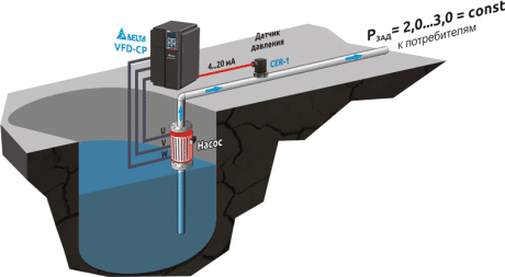
Connection diagram for pressure sensor and dry running. Taking care of the motor: how to protect a submersible pump from dry running and other extreme conditions
Another device that ensures the nominal pressure in your water supply, the correct operation of the pump, and the supply of water is a pressure switch. Based on the name, it can be directly concluded that this unit provides control over the pressure in the system and reacts by turning on, turning off the electrical contacts in case of deviation from the nominal set pressure, within the limits set during its setting. In this article, we want to talk in more detail about the purpose of the pressure switch, about the features during its installation, about settings and characteristics.
Pressure switch application
So, in short, we have already mentioned what a pressure switch can be used for. However, if we talk about specific cases of application, then they include the use of a pressure switch to prevent the “dry running” of the pump, which we wrote about in our other article (“Protection against “dry running” for a well pump using a relay pressure").
Also, the pressure switch maintains pressure in the receiver of the pumping station. As a result, at the outlet, in our faucet, we have a stable, constant flow of water used.
Characteristics of the pressure switch
The main characteristic of a pressure switch is its nominal working pressure. Yes, there is a certain tautology in the previous phrase, but it is precisely this that is fully accurate for describing main characteristic relay, since dimensions, weight, connecting threads are already additional parameters. So, the operating nominal pressure of the pressure switch is an indicator selected from a possible range. So today, according to GOST 26005-83, there is the following working series (controlled pressure MPa (kgf / cm)) for pressure switches:
- 6,3 (63),
- 10 (100),
- 20, (200),
- 32 (320).
In fact, based on the needs of the market and other standards, you may well meet pressure switches with other characteristics for working (control) pressure. Also, the characteristics of the pressure switch should include:
Connecting thread;
- dimensions;
- mass;
- moisture and dust protection class (IP);
- rated current and voltage for switched contacts;
- requirements for the working environment (water, refrigerants, etc.);
- temperature of the working environment;
- version of the pressure switch (built-in sensor or remote)
All this must be taken into account when selecting a pressure switch, for each specific case.
Installation (installation) of the pressure switch
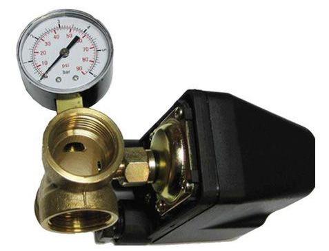
Here, so as not to "spray" on possible options and conditions, of which there can be many, we will give an example for a specific case, for the RDM-5 relay. Installation, installation of the relay can be divided into two stages. The first is the mechanical connection and the second is the electrical connection. The mechanical installation of the RDM pressure switch is carried out using a tee fitting, a control pressure gauge and a FUM tape, which is used for sealing threaded connections(relay has a 1/4" female thread). A photo of the assembly ready for installation in the pipeline is shown below ...
The electrical connections are also not that complicated. The first step is to remove the protective cover of the relay. Under it you will find 4 pins, two "input" and two "output". In the figure below, the electrical supply input is (L1,L2) and the pump output is M
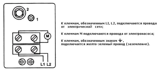
The wire cross section of the supply wires must correspond to the power of the electric pump. The socket must be grounded. Ground must be connected.
As a result, we get the following wiring diagram for the electrical and mechanical parts ...
Let's say right away that such a connection scheme for the pressure switch does not provide protection against "dry running". Protection against "dry running", in case all the water is pumped out of the well, will only work when the pump is higher than the check valve, that is, it enters the pressure control circuit of the relay. But for this case, no longer a submerged pump is required, but a surface one. In general, this is a slightly different option, although also eligible for implementation. See picture below...
Design of the pressure switch (principle of operation)
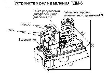
Structurally, most pressure control switches are contacts spring-loaded with a plate, which is affected by the working pressure of the medium. The influence of the plate, the switching on - switching off of the contacts is regulated by changing the stiffness of the spring, which is a direct link providing the dependence of the switching on of the contacts. This screw and springs provide the lower limit for relay actuation. Also, in most cases, there is an adjusting screw with a spring, which provides a spread in the operation (switching on) of the contacts. This screw adjusts the upper limit of the relay operation. Next, we will just talk about setting up the pressure switch, after installation in the water supply system.
Setting (adjusting) the pressure switch
Based on the design features that we talked about earlier, we actually have to set up the dependence, rigidity, between the platform that is affected by the working pressure and the contacts that should be switched on. These adjustments are made by changing the stiffness of the spring, which is actually either compressed or weakened by adjusting nuts. So the factory settings for the RDM 5 relay (as, by the way, for many others) will be as follows. The minimum operating pressure is 1.4 atmospheres, the maximum, which is set using the differential nut, is 2.8 atmospheres. If you need other parameters of the relay actuation, then to increase the level of the lower limit of the contact pressure actuation, tighten the nut 2 clockwise.
Please note that as the lower level increases, the upper shutdown level automatically increases as well. The difference between them will be equal to 1.4 atmospheres. When setting up, it is necessary to observe the condition when the switch-off of the pressure switch must always be lower than the maximum possible pressure delivered by the pump. Otherwise, the pump will never turn off, and in the end, it will simply burn out. For example, it turned out that the shutdown pressure became 4 atmospheres. This means that the lower one will be 4 - 1.4 = 2.6 atmospheres, that is, we raised it from 1.4 to 2.6. Nut 1 is designed to adjust the difference between the minimum and maximum actuation pressure. In our case, at factory settings, this difference is 1.4 atmospheres. If we tighten the nut, then we will increase the difference (for example, instead of 1.4, it will become 2). As a result, it will be necessary to add differential pressure to the lower limit, that is, 2.6 + 2 = 4.6.
It turns out that along with the adjustment of the differential pressure, we also change the upper limit of pressure shutdown. Take this into account when making adjustments. Remember that the maximum shutdown pressure of the pump should not be higher than the maximum output by the pump itself. The settings for reducing the minimum pressure and reducing the differential pressure are directly opposite, that is, nuts 1 and 2 must be unscrewed.
If you try to describe the setting and adjustment of the pressure switch using graphs, you get the following diagram ...
Dry running relay
series RS is intended for continuous monitoring of water pressure and semi-automatic control of an electric pump in private water supply systems built on its basis.
The dry-running relay instantly opens its contacts, turning off the electric pump of the plumbing system when the water pressure drops below the set value, thereby eliminating the “dry running” of the pump, that is, its operation without water.
For normal operation of the dry-running relay, the plumbing system must be equipped with a hydraulic accumulator of any volume.
According to the type of protection against electric shock, the dry-running relay belongs to class I devices.
Specifications:
Maximum switching voltage (at a current frequency of 50 Hz), V:250
Maximum switching current, with active load / with reactive load, A:16 / 8
Set value of contact opening pressure, atm:0,2
Contact opening pressure adjustment range, atm:0...0,6
Set value of contact closure pressure, atm:0,9
Contact closure pressure adjustment range, atm:0,3...1
Degree of protection: IP44 (water splash proof, particle proof > 1.0 mm)
Connecting pipe size:G 1/4 ’’ male thread
The dry running relay consists of the following main elements:
- frame;
- lid;
- pipe branch;
- cable gland;
- relay contact group;
- start button;
- springs with adjusting nuts Р and ΔР;
- plastic cover screw.
Installation
1. By the time the dry-running relay is installed, a pressure switch must also be installed in the water supply system, which will ensure automatic operation of the system's electric pump. The installation of the pressure switch and its connection to the pump must be carried out in accordance with the instructions for its operation.
2. Decide on the installation location of the dry-running relay in the plumbing system. The best place its installation - on the pressure line (at the pump outlet) in the immediate vicinity of the pressure switch.
3. Drain water from the plumbing system at the location of the relay.
4. Remove the cover of the dry-running relay by unscrewing the plastic screw.
5. Connect the dry-running relay socket to the corresponding water supply fitting, using sanitary fluoroplastic tapes or linen with special pastes and sealants.
6. The dry-running relay is included in the break in the power supply circuit of the plumbing system pump. Connection diagram - serial.
7. The dry-running relay can be connected in series according to the scheme both before and after the water system pressure switch. The following describes the connection of a dry-running switch in the circuit “before the pressure switch”.
8. Insert the mains cable and the pressure switch control cable through the appropriate cable glands. All installation work on the installation and connection of the dry-running relay must be carried out only with the mains cable disconnected from the mains!
Good day, dear readers of the blog site
Pressure switch LP-3
In the "Accessories" section, we will consider the "dry running" relay LP3. The LP 3 relay is used as protection against "dry running" in autonomous water supply systems, irrigation and fire extinguishing installations, as well as in air conditioning systems. The operating medium of systems where the LP series relay is used must be water. The "dry running" mode is controlled according to the set pressure values previously set on the relay. The opening of the contacts in the relay occurs when the pressure in the system becomes lower than the preset value. Contact closure occurs when the pressure in the system becomes higher than preset, or when the start button located at the top of the device cover is pressed. Dry running relayLP3 must be used in conjunction with pressure switches RM-5 and RM-12. On sale there are pressure switches LP3 and LP3 / 18 manufactured by an Italian company Italtecnica.
Specifications
Main specifications dry run relay LP3 and LP3/18 are listed in Table 1.
Note:When using a dry-running relay to control pumping equipment, the maximum switching current is 10A.
Relay design
Structurally, the “dry running” relay is assembled in a plastic case and closed with a lid. On (Fig.1) the main elements are indicated.
On the basis of the relay (Pos. 7) all working elements are located. A flange is attached to the base (Pos. 8). We considered the design of the flange in detail in an article devoted to three-phase pressure switches. The flange has a nut with a 1/4″ female thread for connection to a water supply system. By means of a nut and a spring (Pos. 6) the switch-off pressure is adjusted. When the spring is compressed (we tighten the nut), the cut-off pressure will increase. When the spring is unclamped (the nut is unscrewed), the cut-off pressure will decrease. The button (Pos. 5) is used to force the dry running relay into operation. Terminals (Pos. 3 and 4) are used to connect electrical wires. At the same time, it does not matter which terminals are input (~220 V power is supplied) and which are output (motor is connected). For rigid fixation and fastening of the mains cable and the electric cable for connecting the motor, cable clamps (Pos. 1) are used. All working elements of the pressure switch are closed with a cover.
Equipment installation scheme
(Fig. 2) shows the installation diagram of an automatic pumping station using the LP relay.
A non-return valve with a mesh (Pos. 2) is mounted on the suction pipe (Pos. 3). A pressure switch (Pos. 5), a hydraulic accumulator (Pos. 6) and a dry-running switch (Pos. 9) are mounted on the pressure pipeline (Pos. 8). Mounted behind the dry run relay (Pos. 10). Subsequence electrical connections on (Fig. 2): mains plug (Pos. 4) - - dry-running relay and pump motor (Pos. 1). But this sequence can also be as follows: mains plug - dry running relay - pressure switch and pump motor. The basic principle of connecting these two relays is that they must be connected in series.
The principle of operation and adjustment of the "dry running" relay
The device is a two-contact switching relay. Initially, its contacts are in the open state. To start the device into operation, it is necessary to press and hold the red button down until the pressure in the system rises higher than set. When the pressure in the system drops below that set on the relay, the contacts open and the device turns off the pump in the "dry run" mode. The relays are sold with factory-set cut-in pressures (see Table 1). An adjusting nut and spring are used to change the factory settings of the switching pressure (Fig. 1). The more we compress the spring, the greater the switch-on pressure is set to the relay, and when the spring is weakened, the switch-on pressure decreases. It is necessary to control the value of the switch-on pressure on the pressure gauge.
The pump can be called the heart autonomous system water supply. From how responsibly you approached the choice and installation of the device, its uninterrupted functioning depends. However, do not forget about external factors that can adversely affect the operation of the device. Dry running, hydraulic shock, a sharp drop in temperature, electrical short circuit, silting of the well - not the whole list possible causes failure of pumping equipment. How to protect yourself and your family from interruptions in water supply? The answer is simple - take care of the protection of submersible pumps in advance.
The impellers and diffusers of domestic pumps are most often made from thermoplastic. This wear-resistant material copes well with high loads, while in a situation with a “dry run” (work without water), the parts begin to overheat and deform. The result is usually predictable - the shaft jams in the pump or the electric motor burns out. The saddest thing is that in this case there can be no warranty repair (manufacturers emphasize that the devices cannot be used without water).
Dry running protection of the submersible pump is required in the following cases:
- Arrangement of wells and wells with a low flow rate (the volume of water may vary depending on the season).
- Pumping liquid from containers with non-refillable volume (for example, a swimming pool).
- High performance of the pump itself.
So that the device “understands” in time that the water is over and does not work idle, the pump is equipped various types protection:
- Float switch. Inexpensive option for wells (there is not enough space in the well or pipeline for it). The sensor is connected to a phase break, from which the pump is powered, and is set at a fixed level (in case of a critical drop in the water level, the liquid must cover the bottom valve). When the sensor is triggered, the contacts open, "turning off" the power supply to the device. The vast majority of well pumps are equipped with floats.
Pressure switch sensors are installed at several levels
- Pressure switch. The device controls the pressure drops in the system and opens the contacts when the critical point (0.4 - 0.6 bar) is reached, while the pump is restarted only manually. The pressure switch can only be used in combination with a hydraulic tank, otherwise the installation of the sensor will not make sense.
- Press control (flow and pressure switch). Protection of submersible pumps from dry running is carried out using a sensor located in the flow switch. If no liquid passes through the device, it will automatically turn off.
Another effective, but rather expensive way is to install a level switch: three electrodes are connected to the electronic board through a conventional single-core wire and lowered into a well or well shaft. Sensors fixed at different depths give signals about changes in the water level. If it falls below the mark of the control sensor, the motor stops working, if it closes the electrode, the system starts the pump.
Attention! Even if you are confident in the flow rate of the well or have extensive experience in operating pumps, it is better not to take risks and install protection sensors.
Water hammer can damage the pump
Water hammer protection
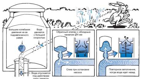
Water hammer can occur when water is drained into the well or the device is turned on after a “dry run”. under high pressure the liquid strongly hits the impeller blades and can damage them. How to protect submersible pump from water hammer? As a rule, manufacturers offer a comprehensive solution:
- Built-in non-return valve, whose task is to compensate for the weight of the water column.
- Hydraulic accumulator equipped with a pressure switch and sensors.
In the event that the pressure exceeds the allowable limits, the system will automatically turn off the device. If this does not happen, then the non-return valve comes into play.
Short circuit protection
Most of breakdowns to one degree or another is associated with the electrical part of the submersible pump. If the voltage in the network is greatly reduced or jumps, there is a high probability of an interturn short circuit of the starter windings (a consequence is the failure of the unit).
To avoid such nuances, many manufacturers equip electric motors with built-in protection. The system turns off when the indicators go beyond the permissible limits and turns on when the voltage returns to normal.
Important! If power surges often occur in your area, it is better to purchase a pump with a system soft start. This device will protect the engine during starting and shutdown.
Automated control systems
Electronic systems solve two problems at once - with their help, protection and control of submersible pumps are carried out. The simplest circuit consists of several multi-level sensors and an electric motor control center; professional stations are used in more complex devices.
The control panel is placed outside the well
Automated system solves the following tasks:
- maintains a predetermined water level;
- protects the engine from "dry running" and power surges;
- turns off the device in emergency situations;
- starts the device after the restoration of indicators;
- smoothly starts and stops the engine;
- blocks switching on in the event of a short circuit.
Many manufacturers produce models with remote control - you can control the operation of the system, even when you are far from home.
Important! No matter how effective electronic system control, it will not be able to protect the pump from freezing or silting of water. Natural risk factors will have to be monitored independently.
When choosing a submersible pump, it is necessary to take into account not only its performance characteristics, but also the parameters of the water intake (depth, diameter, flow rate, static and dynamic water level). If you do not have sufficient experience in arranging wells and wells, it is better to consult with a specialist (at a minimum) or contact a licensed company (at a maximum). You should not save on buying a pump: repairing a budget model can cost you many times more than purchasing a quality device.
Video: pump protection systems
Dry running pressure switch
In the heading "Accessories" we will consider in more detail the algorithm of operation and the device of the pressure switch with protection against "dry running". I already briefly mentioned this product in an article. This device combines both a pressure switch and protection against "dry running". The relay controls, according to pre-set pressure values, turning off and on both well or borehole, and surface pumps when they work together with a hydraulic accumulator. This automation also protects pumping equipment from operation without fluid flow, which allows the user to operate it more comfortably in automatic mode without constant monitoring.
The factory setting for switching off the product in the "dry run" mode is 0.4 - 0.6 bar. If the pressure in the water supply system changes within the specified limits, this resembles the operation of a conventional pressure switch. When the pressure in the system has dropped to a level of 0.4 - 0.6 bar, the device turns off the pumping equipment in the "dry run" mode. Human intervention is required to turn on and continue to operate the pump.
Product Specifications
Specifications pressure switch with dry run protection consider the example of FFSG2G. The main technical characteristics are shown in Table 1.
Table 1
| Characteristics | FFSG2G |
| Operating pressure range (bar) | 1-5 |
| Minimum pressure difference: (bar) | 1,2 |
| Pressure setting range (bar) | 1,4-2,8 |
| Dry run pressure (bar) | 0,4-0,6 |
| Working environment temperature up to (°С) | 55 |
| Maximum operating current (amps) | 16 (10) |
| Supply voltage (volt) | 230 |
| Network frequency (Hz) | 50 |
| Connection internal thread (inch) | 1/4 |
| Protection class | IP44 |
Device, design and principle of operation
The pressure switch with protection against "dry running" is assembled on a metal plate that serves as a housing and is closed with a plastic cover. On (Fig. 1) you can see the internal structure and the main elements.
Housing 1 metal plate - where all the elements of the dry-running pressure switch are located. Connecting flange 2 with 1/4″ internal thread, used to connect the automation to the water supply system. The flange, with the help of six screws, fastens the membrane 9 and nickel 10 to the automation body. The connecting flange, the membrane and the penny, together make up the working chamber. Nut 3 and a small spring that regulate the pressure difference ∆P. This is the difference between the cut-off and turn-on pressures. The more you compress the spring (turn the nut clockwise), the greater the difference ∆Р will be. The minimum difference between the switch-on and switch-off pressures is 1.2 bar. Nut 4 and a large spring are designed to adjust the switch-off pressure. When the spring is compressed (tighten the nut clockwise), the cut-off pressure of the automation increases, and when the nut is released, the cut-off pressure decreases. Terminals 5 and 6 for connecting the pressure switch to the power supply and to the pumping equipment. Bolts 7 for connecting ground wires from the power supply and the engine. Lever 8 starts the pressure switch into operation. Cable sleeves 11 are designed for fastening electrical cables.
Installation, electrical connection and the principle of operation of automation
Installation of this product in the water supply system is no different from standard installation. For the hydraulic part, the automation has a 1/4 inch female connecting thread. The relay can be mounted both on the pipeline itself and on the five-piece. The only condition for installation is that it must be installed next to the automation to prevent flotation inclusions. The capacity of the accumulator depends on the number of points of analysis and the water consumed.
The diagram for connecting the pressure switch to the electrical network is shown in (Fig. 2).
Scheme of electrical connections of automation
pump or pumping station must be plugged into an outlet connected via (RCD). To protect the pumping equipment, it must be provided with a current equal to the rated current of the motor.
Principle of operation next. After completion of all installation work. The system and pump must be filled with water and air must be removed from the pump and suction pipe. We supply power to the pump, but the pump did not start, since the relay contacts are open. To turn on the pump, you need to press the automation start lever and hold it down until the pressure in the system rises above 0.5 bar. After starting, the pump will turn off when the pressure in the system reaches the set pressure on the relay. You can adjust the cut-off pressure of pumping equipment using nut 4 (see Fig. 1). Turning the nut clockwise increases the shutdown pressure of the pump. If the nut is turned counterclockwise, the shut-off pressure of the pump is reduced. It is necessary to monitor the shutdown pressure of the pump by. When water is parsed, the pressure in the system decreases, when the lower level is reached, the automation turns on the pump and maintains pressure in the system. The pressure difference is adjusted using nut 3 (Fig. 1). When the nut is tightened, the difference between the cut-in and cut-out pressure increases, and when the nut is loosened, it decreases. It is necessary to monitor the pressure at which the pump is turned on using a manometer. After the water dissipation stops and the set pressure is reached, the pump will turn off. In the event that water dissipation has begun and for some reason (lack of water, power outage, etc., etc.) the pressure in the system drops below 0.5 bar, the automation contacts will open and the pump will no longer turn on , since the relay has switched off in the "dry run" mode. For the subsequent start of automation, human intervention is necessary. Before putting the relay into operation, you should find out for what reason the pump turned off in a “dry run”. If the water runs out, you need to refill the suction pipe and pump with water, remove air from the pump and pipe. If the problem is in the power supply, you need to fix it and then start the automation again. We press the start lever and wait until the pressure in the system rises above 0.5 bar. Then dry-running pressure switch will continue to operate automatically.
Operation, maintenance and repair
Generally this automation very simple and reliable. If the operating conditions are observed, the relay works without problems for a long time and reliably. However, making adjustments for the quality of our water, the quality of the power supply, or high humidity, performance can be problematic. Problems with the relay very often lead to failure of the pump. To avoid this, it is necessary to check the system and automation periodically and at each restart of the automation.
If the water in the system contains hardness salts or there is a high iron content in the water, during the operation of the automation, the working chamber and flange are gradually “overgrown” with deposits of hardness salts or iron. There comes a time when the relay stops working altogether. To eliminate such a defect, it is necessary to dismantle the relay and clean the chamber from salt deposits by performing the following steps:
- We de-energize the automation and the pump by disconnecting the cord from the power supply.
- We relieve pressure from the water supply system by opening the nearest water tap.
- Disconnect the electrical cables from the automation. To do this, remove the plastic cover from the automation and disconnect the cables from terminals 5, 6 and ground (see Fig. 1)
- We disconnect the relay from the water supply system using an open-end wrench for 17.
- Using a screwdriver, unscrew 6 screws and remove the flange. We clean the chamber and flange from salts.
- We assemble the automation in the reverse order; before installation, it is necessary to seal the threads with fum tape or sealant.
High humidity (oxidation of contacts), fluctuations in the mains voltage (burning of contacts) also leads to interruptions in the operation of automation. In these cases, the automation should be replaced with a new one. Like any technique, a dry-running relay requires attention.
Thank you for your interest.
P.S. Do not miss the opportunity to do a good deed: click on the buttons social networks located below, in which you are registered, so that other people also benefit from this post. BIG ALL THANKS!