
Stations and pump control systems. Electrical diagram of pumping stations. The main tasks of automation of dewatering plants
wiring diagram pumping stations consists of general-purpose electric devices and specialized devices used in automatic control and protection circuits. In the electrical circuits of pumping stations, magnetic starters and automata, contactors and pump motors, alarm devices, control buttons, surge protection devices, and other equipment are widely used.
In addition to the simple contacts available, there are other elements that allow you to perform arithmetic calculations, comparison operations, implement control algorithms, and so on. its great distribution is associated with facilitating the work of users. Figure 6 Ladder type scheme.
This new system able to respond to various situations that can arise and make decisions independently. Figure 6 shows the system automation diagram. Figure 7 System automation. An automated system is a closed flow of interchangeable information, from a control unit to a machine or process, and vice versa. The information received in the control unit is processed and developed in accordance with the control program of each system, from which the actions that will control the operation of the machine or process are obtained.
Specialized devices that help to implement the automatic control system of a pumping station include:
- Pressure switch and liquid level control (float switch);
- Pressure gauges and sensors;
- Fill control relays centrifugal pumps.
The simplest electrical circuit for controlling a pumping unit.
In addition, the control unit can provide already prepared information about the status and evolution of the system to the operator himself. On the other hand, the operator can intervene in the design of the control with the help of slogans that change the parameters of the control algorithm, or he can take control, transferring the control system to manual. Technological evolution has made it possible to realize more complex automated systems, the level of automation has not ceased, since the first and elementary functions of observation, or to link operations usually performed by the operator at the machine level.

Fig.1 Control scheme electrical units pumping station.
The simplest control scheme for a pumping unit can provide for two modes of operation of electric pumps:
- Auto mode;
- Manual control.
The current control mode is selected by the KU key.
From full control of a complex machine to full control of the manufacturing process. Although initially it was only a program that allowed you to control and receive data in management processes, in recent times A series of hardware and bus products has emerged, specifically designed or adapted for this type of system.
Word supervision can be defined as exercising excellent control on certain occasions, with attention or care, and to test a subject for a new examination in order to correct or repair it by resolving the effect of the controlled subject. The work of oversight is a delicate and important task from a regulatory and operational point of view; this action is highly dependent on the quality and efficiency of the process that has been developed. The leader is responsible for directing or correcting the actions being developed.
Manual control:
1. The KU switch selects the manual mode.
2. To start the pumping unit, close the SBC power button and apply voltage to the KM magnetic starter.
3. The magnetic starter turns on and through the contacts KM1 becomes self-holding.
4. The power contacts of the starter supply voltage to the electric motor, the pump unit starts to work.
5. The pump is turned off with the SBT button.
The operator controls the operation of the equipment manually.
Database, data management with low access time. Presentation, graphical presentation of data. Exploitation of the obtained data for quality management, statistical control, production management and administrative and financial management. Alerts the operator to changes detected at the plant, both those that are not considered normal, and changes that occur in the day-to-day operation of the plant. These changes are stored in the system for further analysis.
Generation of factory signals that can be reset for processing on a spreadsheet. Creation of reports, notifications and documentation in general. Execution of programs that change the control law or even general program on the machine. Requirements. They must communicate easily and transparently for the user with the plant equipment and with the rest of the company. It acts as an interface to the operator, including real-time presentation of variable information, alarm administration, collection and presentation of historical information.
Automatic control
1. The KU switch is set to the automatic control position, the SB contact is closed and shunts the self-holding circuit.
2. Contact KK of the float switch is open when the liquid level in the tank is low. The pump is not working.
3. If the liquid level reaches a certain level, the float switch contact closes, the magnetic starter turns on, the pump starts pumping liquid from the tank.
4. When the liquid level in the tank decreases, the KK contacts open, the pump stops.
For example, software for detecting losses in an oil pipeline. Communication network. This is the layer that controls the information that field devices send to the computer network from the system. Field tools: These are all those that allow you to automate or control the system and those that are responsible for collecting information from the system.
The process is geographically distributed. Information about the process is needed at the moment when changes occur in the same, or in other words, information is required in real time. The complexity and speed of the process allows most of the control actions to be triggered by the operator.
Motor protection
To protect electric motors against overload and short circuit currents, a QF circuit breaker with a combined release is used. Protection of the electric motor against voltage failure (zero protection) is carried out by a magnetic starter coil.
Control circuit for two hydraulic units of a pumping station.
Vendors, both hardware and software, can provide products with a high degree of interoperability and interoperability, and users have a wide range of options to build the solution that best suits their needs. This version offers new and significant functionality and many improvements aimed at opening up new possibilities as well as greater value for existing customers and original equipment manufacturers.
On the front panel, where all the indicators and controls that the user can see when the program is running will be displayed. For example, buttons, knobs, graphs, etc. Block diagram. In this, subroutines are shown as black box icons with specific inputs and outputs where a specific function is executed inside.
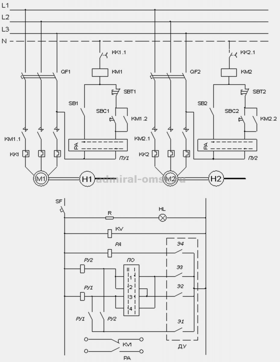
Fig.2 Scheme of automatic control of two pumps.
The control scheme for two pumping units of a pumping station allows you to organize automatic control of the pumping station without the participation of on-duty personnel. The electrical circuit of the pumping station includes 2 hydraulic pumps. One pump is operating normally. The second pump is on standby and is automatically switched on if the first one fails to cope with the load or fails. Which of the pumps is currently operating in the operating mode, and which is the standby one, is determined by the software pumping mode switch:
It is used to use a program created as a subroutine in another program, where the icon will be a black box and the inputs will be connections to the program programs of the subroutines and the outputs will be connections to the indicators of the same subroutine.
There are two types of data, unstructured and structured. Each anchor point in the control panel has a drawing on the block diagram. Unstructured or scalar data: This type of data is characterized by the fact that it cannot be divided into other smaller components. These types, called standard types, should not be defined in the program as they are assumed to be known and include booleans, integers, real numbers and character sets. An example of them can be seen in the figure.
- the first position of the switch - in the operating mode pump 1;
- second position - pump 2 is in operating mode.
The scheme allows you to automatically control the electric motors of hydraulic units with permanently open outlet plugs. To determine the water level in the tank, the circuit uses a four-level electronic level sensor DU. Its contacts E1, E2, E3, E4 give control commands to start and turn off the engines of the water supply system.
Consider the operation of the circuit in automatic mode, with a working pump 1 with an engine M1. Software switch in 1 position. Contacts 1, 3 of the cut-off switch are closed, but relays RU1, RU2 do not work, since their circuit is open by contacts E2, E3 of the remote control sensor. If the liquid level rises to the level of sensor E2, the relay coil circuit RU1 closes. The relay is activated. Its contact RU1 closes, which supplies voltage to the coil of the magnetic starter. The magnetic starter with its contacts KM1.1 supplies power to the pump motor M1. The electric pump H1 starts and starts pumping.
Structured data: A structured coordinate system is defined as a set of variables collected under one common name. These data structures are built from the primitive data types already seen in the previous section. Structured Programming: Structured programming is based on the use of four sets of structures: Sequence: A sequence structure consists of a series of elementary actions that are performed in the order in which they are described.
Conditional: A conditional structure is used when two or more alternative actions depend on a condition. If it is false, it will never be executed. Subroutines have the same properties as a program and are used to create icons and connectors that make it easier to read and interpret the global virtual instrument. The project will use a combination of both programs, both modular and structured.

In normal mode, the water level in the tank drops, the E2 contact circuit breaks, but the engine continues to run. It will only turn off when the level water will fall below contact E1. This is done in order to avoid frequent on-off cycles of the engine with a slight fluctuation in the liquid level near the level of contact E2.
If the performance of the pump H1 is not enough or it is out of order, the liquid level will rise and close the contacts of the sensor E3, which will supply power to the relay coil circuit RU2. As a result, voltage will be applied to the magnetic starter PM2, the contacts of which will ensure the start of the electric motor M2 of the backup unit. The backup pump will turn off when the level drops below contact E1.
This thought had to change among the company's designers, who have given the importance of using a universal language for programming automata. Thanks to new graphical tools, communication can be more easily configured. Support for standard 10-bit modems and easier integration into a communication network. Documentation and printing of projects. Block titles and comments with time and date. Significant improvements to the print function, including multiple page previews.
Flexible print configuration that allows you to include and exclude project parts such as program block, data block, and symbols and status tables. The introduction of technology has allowed man to transport water more easily, making progress in the development of controls.
If the liquid level for any reason reaches the maximum allowable level, contact E4 closes. This will activate the alarm relay PA, which will notify personnel of the abnormal condition. Voltage control in the circuit is carried out using the RKN relay. Signaling circuits are powered by guaranteed power buses. The HL lamp indicates the presence of voltage in the pump control circuits. If necessary, you can transfer the pumps to manual control and control the processes of switching on and off manually.
Pumping system drinking water, which provides this vital fluid, needs good equipment for its operation, as well as in good control to improve the service to the end user. Because the size of the system is directly related to the product of the total dynamic load and the required daily volume. The total dynamic load is the sum of the static load and the dynamic load: Static load The first part, the static load, can be obtained by direct measurements.
This is the vertical distance that water travels from the loss level of the well to the height at which the water is discharged. The static load is the sum of the descent, the static level, and the height of the discharge. All wells experience a struggle phenomenon when water is pumped, this is the distance that the water level is lowered due to the constant extraction of water. In FIG. 17 shows these hydraulic components that make up the static load. Dynamic Loading Dynamic loading is the increase in pressure caused by resistance to flow in water due to roughness of pipes and components such as elbows and valves, this roughness depends on the material used in the manufacture of the pipes.

Pump station valve control scheme
Consider the scheme of a pump valve, which is controlled through a gearbox by a small-sized asynchronous electric motor. When the voltage is applied to the circuit, the green lamp starts to glow halfway. It signals the closed position of the plug. The pumping unit is started by the level switch RU. One of the contacts of the switchgear gives a command to start the electric motor M1 of the pumping unit, and the second closes the circuit of the relay coil RP1, which controls the operation of the motor plug M2.
In order to calculate the dynamic load, it is necessary to find the distance that water travels from the point where the water enters the pump to the point of discharge, including horizontal distances, as well as the material of the conduction line and its diameter. These are mostly irreplaceable elements, but if you want to automate, the constituent elements increase in number according to the purpose of the specified automation. Pumps The pump is used to obtain the amplification factor in the static charge of the liquid coming from the mechanical energy transmitted along its axis with the help of a motor.
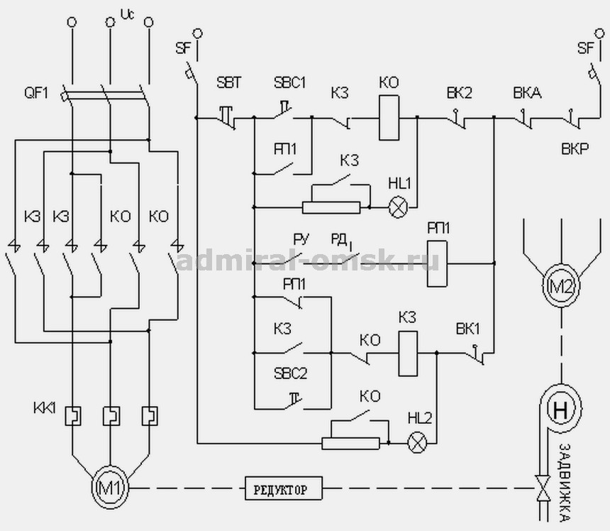
After starting the pump and increasing the pressure in the plumbing system to a normal level, the contact of the pressure switch RD is closed, connected in series with the contact switchgear in the RP1 coil circuit. Relay RP1 pulls up, closes the normally open contact and energizes the valve opening contactor KO. The contactor starts the M2 motor to open the valve. The valve opening process is controlled by the VK2 limit switch, as well as by a bright red lamp. After the valve is fully opened, the VK2 contacts will open, the KO will turn off, the valve control motor will stop. The red lamp will burn half-heartedly, and the green lamp will go out completely. The valve closing scheme works similarly. For emergency shutdown of the control circuit, the VKA emergency switch is used. When the switch is activated, both signal lamps go out.
There are many pumping mechanisms, the power, design and application of which cover a wide range: from small units used to dispense minimal quantities, to centrifugal pumps that are able to handle large volumes to deliver water in large concentrations in cities. Its diverse designs cover various operating principles, special pumps for handling materials as diverse as water, molten metals, concrete, various costs and Construction Materials, since the system you want to automate already learns these elements, they will not be performed in this work.
Send your good work in the knowledge base is simple. Use the form below
Students, graduate students, young scientists who use the knowledge base in their studies and work will be very grateful to you.
Posted on http://www.allbest.ru/
Ministry of Education of the Moscow Region
State budget educational institution
Secondary vocational education
Moscow region
"Klin Industrial and Economic College"
Abstract on the topic:
"Automatic control of pumping stations"
Fulfilled
student gr. TM-11
I.S. Karelin
Purpose and principle of operation of pumping stations
A water supply pumping station is an indispensable part of the water supply system in a house or cottage if it receives it from autonomous sources such as deep wells. In some cases, these units are also used for pumping water from the water supply network, when the pressure in it is not enough, and also, if desired, to have its supply in storage tanks. Pumping stations for the home and for summer cottages easily cope with the lifting and supply of deep waters, and, if necessary, can pump water over considerable distances. All operations, as well as control over them, including ensuring the safe operation of the system, eliminating water hammer, etc., are performed in a fully automatic (or semi-automatic) mode. Unlike submersible well systems, an automatic pumping station is located on the surface. It is a pump connected in a monoblock with a relay pump and a hydraulic accumulator. Water enters under pressure, and when the latter drops to a certain threshold, the relay automatically turns on the pump to repeat the cycle. Before you buy a pumping station, the closest attention should be paid to the selection of a hydraulic accumulator. Its volume is related to water consumption and must be optimal, since only in this case is guaranteed long-term reliable operation of the entire system as a whole. Sewage pumping stations are allocated into a separate category, which also include a special container for trapping solids. Even more effective is the use of a special pump with an integrated cutting mechanism, which serves to grind large particles and fibers.
General information. Work of pumping installations of the electric power. In modern domestic and foreign systems, the regulation of operating modes of pumping units is carried out by means of an automated adjustable electric drive. In such systems, the controlled parameter is the pressure of the liquid. Modern development of technology allows you to maintain a given pressure with great accuracy. However, high accuracy entails a continuous change in the rotational speed of the electric motor of the pump unit and, as a result, contributes to the occurrence of alternating loads on individual elements of the pump unit (elastic couplings connecting the pump to the engine, etc.), leading to their premature wear. Therefore, in some cases it is necessary to set an increased dead zone of the control system, which reduces the accuracy of head stabilization.
As an adjustable electric drive of a pumping unit in a hot water supply system, it is planned to use one of the types of an electric drive, including: inductor slip clutches (IMS) with excitation power from thyristor blocks BU-3509 and the like; frequency converters of the PChT, PHR-2 SAMI series (Stromberg) and other types; electric drives according to the AVK scheme based on TDP-2 converters and control stations ShDU; electric drives based on valve motors with converters PCHVN, PCHVS.
Stabilization of the liquid pressure is carried out due to the fact that with a decrease in water intake, the pressure in the network increases, and the speed of the pump motor decreases as a result of the control system. With an increase in water consumption, on the contrary, the pressure of the liquid in the network drops, and the rotational speed increases. The main purpose of the liquid pressure stabilization system in the piping system is to maintain the pressure at a given level.
In systems for stabilizing pressure in the network, it is necessary to provide for the inclusion of additional unregulated pumps with a significant increase in inflow or water consumption and their shutdown when it decreases.
The largest pump units with the most gentle characteristic should be equipped with an adjustable drive. In the case of using the same type of pumps, in order to avoid the formation of dead zones, impellers of unregulated pumps must have diameters smaller than adjustable ones. If the diameters are equal and the adjustable pump operates in the maximum flow mode with an increased rotational speed (in the case of using a frequency electric drive), it must be equipped with an increased power motor in accordance with the recommendations.
Despite the obvious advantages, the controlled electric drive has not yet become widespread in pumping installations. Currently, there are conditions that require its wider use. The rapid development of semiconductor technology has made it possible to create reliable and relatively inexpensive adjustable electric drives based on static converters. In addition, the global energy crisis has clearly demonstrated the true value of energy resources and stimulated measures for their rational use. As a result, research, development and creation of pumping units equipped with an automated adjustable electric drive has expanded.
The systems are designed for automatic and manual control of a group of pumping units with asynchronous electric motors operating in water supply or sanitation systems in order to maintain a given water pressure in the main line or the level in process tanks.
Capabilities of automatic control systems for pumping stations:
· Automatic, manual and remote control of pump units;
Collecting information about the state of each control object;
· Collection of information about the state of the parameters of the input and output lines, levels;
· Management of shut-off and control valves in automatic, manual mode and remotely by the dispatcher;
· Displaying information about the state of objects in a graphical editor on the screen of the control room;
· When operating in automatic mode, monitoring of operating hours for each pump.
Stations provide:
· Save energy consumption (not less than 50 ... 65%) and reduce water consumption;
· Restriction of starting currents in a network;
· Increase in a resource of electric motors of pumps;
· Reducing the number of on-duty and maintenance personnel.
The use of ejectors in pumping stations
Pumping stations for wells are equipped with either built-in or remote ejectors, which are connected to a centrifugal jet pump. Ezhector- a device in which kinetic energy is transferred from one medium moving at a higher speed to another. Ejector working on lawBernoulli, creates a reduced pressure of one medium in the narrowing section, which causes suction into the flow of another medium, which is then transferred and removed from the place of absorption by the energy of the first medium. The first option has increased reliability, while it is possible to obtain a large pressure with sufficient pressure for practical application suction depth. Built-in ejectors are especially useful in "needle" wells, which are a pipe driven into the ground to the aquifer. In the second version, the water pumping station uses the same types of pumps, however, the ejectors are not built-in, but remote, which makes it possible to successfully raise water from wells with a depth of up to 50 meters or more. The main unit is located outside, and the two-pipe ejector goes down to the bottom. Most often, such a water supply system is used at a significant distance from the well to the consumer. Its disadvantage is its criticality to water pollution and relatively low efficiency.
On the producers of pumping stations.
The recognized world leaders producing the best industrial and domestic pumping stations in terms of price and functionality are the Italian companies Marina and Calpeda. The advantages should include:
Reliability
Noiselessness in work;
ease of connection and use;
sufficient the lineup;
Completed set;
· compactness;
Simplicity and thoughtfulness of automation;
· Availability effective means protection;
Significant motor resource.
The price of a pumping station depends on its capabilities. The following series are in greatest demand among buyers:
· SeriesCAM for water supply from wells from a depth of up to 9 m;
· SeriesAPM for water supply from wells from a depth of up to 25 m;
· Idromat series automatic system based on the Idromat controller.
· BS series. Booster stations with up to 6 pumps;
· SeriesMINIMAT, TURBOMAT, CENTRIMATandGETTOMAT. Automatic systems With membrane tank;
· EASYMAT series. Compact installations.
Pumping station with controlled electric drive based on IC
The expediency of using ACS with a controlled electric drive in pumping stations, taking into account the ratio of prices for equipment and electricity in our country and other factors, is justified in the works of VNIIVODGEO. An experimental verification of these assumptions was carried out at the Ivanovskaya pumping station in Moscow. At this station, two of the six pumping units installed were equipped with mass-produced ICs. Nominal parameters of the units: supply 800 m3/h (0.22 m3/s), head 33 m (0.33), power 160 kW, rotational speed 960 rpm, torque IKS 1, 60 kNChm (160 kgf/m ). The regulation of the operating mode of the installation without an adjustable electric drive was carried out by periodically switching on and off: pumping units. The number of inclusions was 30-40 per day, and the number of operating units, depending on the inflow, varied from 1 to 6. The automatic control system changes the rotational speed of one or two adjustable units and the total number of operating units in accordance with the change in inflow. The rotation frequency changes according to the deviation signal generated when the level goes out of the specified limits. The deviation signal, processed according to the PI law, is fed to the input of the pulse-phase control system of the thyristor exciter IC. This regulates its excitation current and, accordingly, the speed of the pump motor. With significant changes in the inflow, when a change in the speed of the adjustable pump does not provide the required change in the supply of the pumping unit, it becomes necessary to change total number units working at the station. For this, a block of interaction between regulated and unregulated units is used. The block turns off the spin from unregulated units and forces the excitation of the ICS to the maximum current value (5 A) at the moment when the speed of the regulated pump becomes so low that its check valve closes and the pump stops pumping. If the frequency of rotation of the regulated pump reaches its maximum value, and the inflow continues to increase and the installation cannot cope with pumping wastewater from the tank, the unit additionally turns on one of the unregulated units and reduces the excitation of the IC to a minimum. The system provides level stabilization in the pumping station tank with an accuracy of 50 mm and short-term deviations (up to 350 mm) when connecting or disconnecting an unregulated pumping unit. The system allows you to control the speed of several, in this case two, units at the same time. The need for this mode of operation arises when the inflow slightly exceeds the supply of one pump. Under such conditions, the parallel operation of the regulated and unregulated units is unstable, since the load of the regulated unit is only 5-10% of the nominal value. The resulting slight changes in the inflow entail the switching on and off of the unregulated unit. As a result, significant disturbing effects are created, which cannot always be removed by the control system. Synchronous operation of two adjustable units, equivalent to the operation of one high-power unit, prevents the occurrence of unstable operating modes. The introduction of the regulation system allowed to reduce electricity consumption by about 10%, i.е. by 170,000 kW per year, as well as the number of switching on of pumping units from 30 to 3 per day.
An increase in the efficiency of the LPU is provided by the introduction of a device that changes the number of operating units before the regulated pumping unit enters the zone of unacceptably low efficiency. Such a device was developed at VNIIVODGEO and was tested at one of the existing Moscow pumping stations. At the same time, operating experience has revealed the extremely low reliability of ICs mass-produced by our industry, which does not allow us to recommend them for widespread implementation until they are brought into line with the best samples of ICs manufactured by foreign companies. Several control systems were tested at the facility: with discrete and analog level converters of various types. In the conditions of pumping stations, analog converters with an air bell turned out to be the most reliable.
Pumping station with a controlled electric drive according to the AVK scheme
In Moscow, the SPU of the Kuntsevskaya pumping station has been operating for a long time, at which six pumping units with a capacity of 800 kW, including 3-4 working ones, have been installed. The automatic control system consists of one asynchronous electric motor with a phase rotor with a power of 800 kW and a rotation speed of 740 rpm, an AVK converter, the functions of which are performed by the TDP2ZO4OO-T unit, consisting of a rectifier and an inverter, a smoothing choke FROS-800, a matching transformer TS4OO, a station P3DU90248A control and starting resistors, a level converter consisting of an air bell and a differential pressure gauge; PI controller. The system stabilizes the liquid level in the tank with an accuracy of 7-10 cm. Higher accuracy of level stabilization entailed increased wear of the fingers of the elastic coupling connecting the electric motor to the pump. Increased wear is due to the excitement of the liquid in the tank (wave height of 20 cm), which required an increase in the dead zone of the ACS and a decrease in the accuracy of level stabilization. The principle of operation of the unit speed control system is similar to that described above. Changing the number of pumping units operating at the station is carried out by operational personnel. The use of this system in a pumping unit saves annually 600,700 thousand kWh of electricity, thus approximately 4-5% of the total energy consumption.
Additional capital costs due to the use of the control system in the pumping unit amounted to 15 thousand rubles. The adjustable pump unit is used during the year up to 5000 hours.
At present, in order to increase the efficiency of the ACS and reduce wear of the adjustable pump unit, it is planned to equip one more pump with a controlled electric drive of the same type.
Pumping stations with frequency drives
In the Mosvokstroy pumping station (Moscow), a conventional squirrel-cage asynchronous pump motor with a power of 110 kW / h is connected through a PCT converter developed at the Research Institute of KhEMZ. The electric drive control system is built similarly to the previously described ones, except that the ECHO3 ultrasonic level gauge is used as a level transducer in the system. The use of a frequency electric drive in this installation reduces electricity consumption by 60 thousand kWh per year, thus. by about 5%.
Pumping stations in Moscow also use frequency converters of the PCR-2 type and manufactured by the Finnish company Stromberg, on the basis of which more than 10 automatic control systems for the operation of pumping stations with units with a power of 75 to 160 kW have been created and are operating. The control system using a Stromberg SAMI frequency converter has been in operation for a long time at the Novo-Nagatinskaya station, saving 7-8% of its total electricity consumption.
Stromberg frequency converters are highly reliable and rather compact means of pump unit control. To ensure uniform use of the pump units, a device is provided with which they can be connected in turn to one converter.
There are known cases of using domestic frequency converters of the PCT type in Kharkov, the EKT type in Leningrad, etc.
Pumping station with a drive based on a permanent magnet motor
electric drive pumping station
At the Filevskaya pumping station in Moscow, an automatic control system was introduced using an electric drive based on a permanent magnet motor. Of the six pumps of the 30-FV-17 brand installed at the station, one of them is equipped with such an electric drive using a PCHVN converter developed by the Research Institute of Khemz. Electric drive power 1600 kW, motor voltage 10 kV. The converter is connected to the power supply network through a step-down dry transformer with a capacity of 4000 kWh, and the motor is connected to the converter through the same step-up transformer. The converter also includes a thyristor power converter for the excitation system of a synchronous electric motor, which was not replaced during the introduction of the electric drive. The pump electric drive control system is similar to those described above. An air bell and a differential pressure gauge with a 0-5 mA output were used as a level sensor. The control system used PI-regulator type P-17. The use of ACS with a controlled electric drive reduced electricity consumption by approximately 1,200 thousand kWh per year, improved the operating conditions of pumping equipment, and facilitated the working conditions of operational personnel. The analysis of the ACS operation and the performed calculations show that equipping the second pumping unit with a similar electric drive would make it possible to almost double the energy savings. At the station, a device was tested that excludes the operation of an adjustable pump in the zone of low efficiency.
Hosted on Allbest.ru
...Similar Documents
The use of pumping stations for pumping industrial wastewater, their design as separate or in a block with industrial premises. Selection of auxiliary equipment. Technical and economic calculations, safety measures.
term paper, added 09/01/2014
Initial data for the technological calculation of the oil pipeline. Mechanical characteristics of pipe steels. Technological calculation of the oil pipeline. Characteristics of the pipeline without looping and pumping stations. Arrangement of pumping stations on the route profile.
term paper, added 03/04/2014
Development of a control system for a pumping station based on a frequency converter. Calculation of the electric motor and its mechanical characteristics. Frequency converter selection. Economic effect and payback period of the proposed solution.
thesis, added 01/08/2012
Pumping and blower stations as the main energy links of water supply and sanitation systems. Calculation of the operating mode of the pumping station. Choice of brands of household pumps. The layout of the pumping station, the choice of additional equipment.
term paper, added 12/16/2012
The main purpose of the reclamation station, its design. Features of irrigation pumping stations. The data underlying the project. Structural description of the structure node. Selection of hydromechanical, power equipment.
test, added 11/30/2012
Stages of development and operation of an oil field. Collection and transportation of well products at the Lovenskoye field. Appointment of booster pumping stations, process flow diagram. The principle of operation of a sectional centrifugal pump.
term paper, added 03/27/2016
Design of main gas and oil pipelines, route selection main pipeline. Technological schemes of compressor stations with centrifugal non-full-pressure superchargers. Joint operation of pumping stations and the linear part of the oil pipeline.
term paper, added 05/17/2016
Characteristics of the structures of oil pumping stations and compensators. The main causes of equipment failures are related to vibration. Development of measures to reduce vibration by introducing bellows universal lens compensators into the pump piping.
thesis, added 05/16/2017
Analysis of the use of sucker rod pumping units (SHSNU) in modern conditions. Scheme of the SHSNU device, calculation, selection of equipment. Downhole rod pumps, their purpose and recommended scope. Characteristics of the work of pumping rods.
test, added 01/19/2016
Classification of gas distribution stations (GDS). The principle of operation of the GDS of individual design. Technological scheme of block-complete gas distribution station of the BK-GRS-I-30 brand and automatic gas distribution station of the AGRS-10 brand. Typical equipment of a gas distribution station.