
Hydraulic resistance to flow. Hydraulic resistance and their calculation. Influence of flow regime in pipes on hydraulic losses
DEFINITION
hydraulic resistance called the loss of specific energy during its transition into heat in the areas hydraulic systems, which are caused by viscous friction.
In this case, these losses are divided into:
- losses arising from the uniform flow of a viscous fluid through a straight pipe having a constant cross section. These are the so-called friction losses along the length, which are proportional to the length of the pipe. The resistance along the length is caused by the forces of viscous friction;
- losses that are generated by local hydraulic resistances, for example, changes in the shape and/or size of the channel, which change the flow. These losses are called local. Local resistances are explained by changes in the flow velocity in magnitude and direction.
Losses in hydraulics are measured in units of length when talking about head loss () or in pressure units ().
If the flow is turbulent, then the effective hydraulic conductivity will be much lower than predicted by Darcy's law. And it changes directly with the viscosity of water, which, in turn, depends on the temperature of the water. Table 3 Physical Properties water.
This effect has already been considered in the previous safety factor recommendation. The hydraulic conductivity in the equations also depends on the number and size of the gaps in the medium used for the wetlands. Hydraulic conductivity is recommended to be measured on the ground or in a laboratory prior to final construction.
Darcy coefficient for laminar fluid flow
If the liquid flows uniformly through the pipe, then the head loss along the length () is found using the Darcy-Weisbach formula. This formula is valid for round pipes.
It is desirable that the porosity of the media is also measured in the laboratory before making the final design. A relationship based on the Ergun equation can be used to estimate hydraulic conductivity when using heavy gravel or rock.
This equation, as well as the values in Table 4, are only useful for preliminary design or order of magnitude estimation. The tentative recommendation that the hydraulic gradient be limited to no more than 20% of the available load loss is a partial effect of limiting the system shape ratio to relatively low values.
where is the coefficient of hydraulic resistance (Darcy coefficient), is the free fall acceleration, d is the pipe diameter. The coefficient of hydraulic resistance () is a dimensionless value. This coefficient is related to the Reynolds number. So for a pipe in the form of a round cylinder, the coefficient of hydraulic resistance is considered equal to:
The following hydraulic analogy will help us somehow understand the significance of the potential fall of electrical circuits. Thus, there is a gradual loss of pressure along the tube. The pressure difference between two points is what is needed for fluid to flow between those two points.
By opening the valve a little more, of course, more water will flow: the pressure will decrease in equal proportion. Components of hydraulic systems. The main purposes of hydraulic fluid are. Efficiently transfer the power provided to you.
In laminar flow to find hydraulic friction at Re2300, the formula is used:
For pipes, the cross section of which differs from the circle, the coefficient of hydraulic friction is taken equal to:
where A=57 if the channel section is square. All the above formulas are valid for laminar fluid flow.
Hydraulic resistance coefficient in turbulent flow
If the flow is turbulent, then there is no analytical expression for the drag coefficient. For such fluid motion, the drag coefficient as a function of the Reynolds number is obtained empirically. For a round cylindrical smooth pipe, the considered coefficient at is calculated by the Blausius formula:
Cool system components. Satisfactorily lubricate internal components. Seal gaps between moving parts. Characteristics of hydraulic fluids. This is a measure of the resistance it offers when flowing at a certain temperature. In mineral oil, it changes inversely with temperature, i.e. as the temperature rises, the viscosity decreases. For this reason, one of the factors preventing the choice of fluid is the operating temperature range of the hydraulic system.
The hydraulic fluid should be as low as possible to minimize pressure losses in the piping and penetrate component gaps to lubricate them, but should not be so low as to cause leakage between high and low pressure areas.
![]()
With turbulent fluid motion, the coefficient of hydraulic friction depends on the nature of the motion (Reynolds number) and on the quality (smoothness) of the pipe walls. The roughness of the pipes is estimated using a certain parameter, which is called the absolute roughness ().
Viscosity is selected depending on the type of pump and operating temperature systems. The low viscosity reduces energy loss and penetrates component lubrication gaps, but can cause leaks. High viscosity causes suction difficulty on the pump and loss of energy.
There are several viscosity scales and different types of viscometers standardized according to each scale. This standard uses kinematic viscosity to determine viscosity. Used for industrial oils. Used for motor oils.
The test measures the time a certain volume of oil flows through a capillary tube under the force of gravity at a standard temperature. This figure depends on the type of oil, its production and its addition. Demetricity: The ability of a liquid to separate from water. Hydraulic fluids that do not contain water must have good demulsibility so that free water can be drained from the system. Water pollution occurs due to condensation, leaks in heat exchangers and moist air entering through the vent.
local resistance
Local resistances generate changes in the modulus and direction of fluid velocity in certain sections of the pipe, and this is associated with additional pressure losses.
The coefficient of local resistance is called a dimensionless physical quantity, often denoted as, equal to the ratio of the head loss in the considered local resistance () to the velocity head ():
Mineral oils Mineral oil, derived from petroleum, is the most commonly used fluid in hydraulic systems. It has excellent properties and can be used in many different types of systems and under the most difficult operating conditions. It has the following characteristics.
It is compatible with all elements used in the system. It has viscosity characteristics that meet the requirements of the pump and all system components. It has good lubricating characteristics, supporting high loads and avoiding wear on moving parts.
![]()
The value is determined experimentally.
If the fluid flow velocity in the entire section is constant and equal to , then the local resistance coefficient can be determined as:
![]()
Protects components from corrosion and rust. They are resistant to foam formation and air absorption, easily separating from water. The main additives in hydraulic oils that improve the properties of oils are. Antioxidants: They delay oxidation, increasing fluid life.
Defoamers: These provide the fastest deaeration. Introducing air into the system due to lack of oil or sealing problems will cause foaming, leading to cavitation and system malfunction. Relevant points when choosing a hydraulic fluid.
All hydraulic energy losses are divided into two types: friction losses along the length of pipelines (discussed in paragraphs 4.3 and 4.4) and local losses caused by such elements of pipelines in which, due to a change in the size or configuration of the channel, a change in the flow rate occurs, separation of the flow from the walls channels and the occurrence of vortex formation.
Have minimal change in viscosity with temperature. Protect metal surfaces from corrosion and rust. Lubricate and protect from moving parts. Do not react with system materials. They have a high heat transfer coefficient. Easy to separate from water.
Release trapped air quickly. The frequency of changing hydraulic oil depends on its quality, type of work and level of contamination, the experience of manufacturers and users shows some parameters. Contamination of hydraulic fluids. Contaminants cause problems related to the acceleration of oxidation, the destruction of the molecular structure, the formation of tar residues and varnishes. As a consequence, the service life of the fluids is reduced due to the decomposition of the additives and the lowering of the operating temperature. The detrimental effects of lack of lubrication affect not only the components of hydraulic systems, but also the final cost of the process and the products and services produced.
The simplest local hydraulic resistance can be divided into widenings, narrowings and turns of the channel, each of which can be sudden or gradual. More complex cases of local resistance are compounds or combinations of the listed simplest resistances.
Let us consider the simplest local resistances in a turbulent flow regime in a pipe.
Consequences of poor filtration. Losses in production from unwanted stoppages. Frequent replacement of components and fluids. Reduced component life. Increased maintenance costs. Wear on balls and valve seats. Put on the seal pins and shirts.
Clogging of holes and wear of the spool. Coil binding causing malfunctions in the solenoid. Orifice erosion causing changes in valve control characteristics. Wear resistant pumps and valves. Reduced efficiency of pumps, galling in blades, gears or cylinders.
1. Sudden expansion of the channel. The loss of pressure (energy) during a sudden expansion of the channel is spent on vortex formation associated with separation of the flow from the walls, i.e. to maintain the rotational continuous movement of liquid masses with their constant renewal.
Rice. 4.9. Sudden expansion of the tube
With a sudden expansion of the channel (pipe) (Fig. 4.9), the flow breaks off from the corner and expands not suddenly, like a channel, but gradually, and vortices form in the annular space between the flow and the pipe wall, which are the cause of energy losses. Consider two flow sections: 1-1 - in the expansion plane of the pipe and 2-2 - in the place where the flow, having expanded, filled the entire section of a wide pipe. Since the flow between the sections under consideration expands, its velocity decreases, and the pressure increases. Therefore, the second piezometer shows the height at Δ H greater than the first; but if there were no pressure losses in this place, then the second piezometer would show a higher height by another h ext. This height is the local expansion head loss, which is determined by the formula:
These are physical elements that allow the removal of contaminants from liquids in order to keep them performance characteristics. To remove impurities, the liquid is fed through a filter element that retains the contamination. Its presence is mandatory, so it is important to understand its characteristics.
Preventive maintenance in hydraulic systems - best tool to prevent losses and unwanted stops. Proper fluid storage and handling is essential to prevent contamination and preserve the working environment. Manufacturers of hydraulic power packs already specify the amount and type of fluid to use, but often due to conditions environment, operation and Maintenance fluid must be adjusted to get better system performance.
![]()
where S1, S2- cross-sectional area 1-1 and 2-2 .
This expression is a consequence Borda's theorems, which states that the head loss during a sudden expansion of the channel is equal to the velocity head, determined from the difference in speeds
![]()
Any type of hydraulic fluid, lubricant or coolant must be disposed of by qualified companies accredited by the environmental authorities. Technical support lubricant suppliers is fundamental to the good performance of hydraulic systems.
Watertightness, strength, durability and ease of installation are some important properties in the construction of hydraulic systems, whether cold or hot water. In addition to the price, pipe and joint technologies differ in the method of assembly and its resistance to pressure and temperature.
Expression (1 - S 1 /S 2) 2 is denoted by the Greek letter ζ (zeta) and is called the loss factor, thus
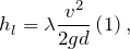
2. Gradual widening of the channel. A gradually expanding pipe is called a diffuser (Fig. 4.10). The flow of velocity in the diffuser is accompanied by its decrease and increase in pressure, and, consequently, the conversion of the kinetic energy of the liquid into pressure energy. In the diffuser, as in the case of a sudden expansion of the channel, the main flow is separated from the wall and vortex formation occurs. The intensity of these phenomena increases with increasing diffuser expansion angle α.
The most recent developments in this area in Brazil indicate an increased use of flexible pipes, especially for hydraulic kits, in jobs with a higher degree of repetition, such as commercial, residential and hotel buildings.
Regardless of the system chosen, it is important to draw up a detailed design to guide implementation and reduce losses, which can range from 5% to 25% in the case of pipes and from 0.5% to 2.5% in the case of a connection. Among them - the organization of stocks of pipes and stocks of connections; ability to use most pipes for the manufacture of each part of the pipe, avoiding the residual ends of the pipes; control over available connections at the construction site; knowledge of the details of the implemented system to avoid repetitive work; the possibility of preliminary execution of parts of the system on the bench; and knowledge by the worker of the correct technology for the accepted material.
Rice. 4.10. Gradual expansion of the pipe
In addition, there are the usual thorn losses in the diffuser, similar to those that occur in pipes of constant cross section. The total pressure loss in the diffuser is considered as the sum of two terms:
where h tr and h ext- loss of pressure due to friction and expansion (vortex formation).
Hot water Among the materials used in the hot water distribution network, copper is the most common, mainly due to its characteristics such as reduced thermal expansion, high resistance to service pressures and resistance to mechanical and thermal fatigue.
For example, in residential and commercial buildings, this material can be found throughout the building, but mainly in the distribution network, supplemented by a copper plumb line. The advantage of combining materials is cost savings and increased productivity. Systems for hot and cold water in building installations.
![]()
where n = S 2 /S 1 = (r 2 /r 1) 2 - the degree of expansion of the diffuser. Expansion head loss h ext is of the same nature as in the case of a sudden widening of the channel
![]()
where k- softening factor, at α= 5…20°, k= sinα.
It is a material that can be rigid or flexible without compromising the viability of water and is lightweight and insulating. Parts can be welded or cut. At present, the weldable joint system is most commonly used because it is easier to make. However threaded connection most suitable for work when line wiring is required for design changes or maintenance.
Therefore, it is more resistant to the conduction of liquids under pressure and at more high temperature. Copper Employees conducting hot water, copper pipes and fittings, often meet the requirements of this type of application, such as high strength and durability and low roughness. The welded joints used in the joints also provide water tightness, and copper, in addition, is recyclable and has good thermal conductivity. To ensure the long life of installations, it is important that the connections are useful.
Given this, the total head loss can be rewritten as:
whence the drag coefficient of the diffuser can be expressed by the formula

Rice. 4.11. Dependence of ζ diff on the angle
Function ζ = f(α) has a minimum at some most favorable optimal value of the angle α, the optimal value of which is determined by the following expression:
![]()
Substituting into this formula λ T=0.015…0.025 and n= 2…4 we get α wholesale= 6 (fig.4.11).
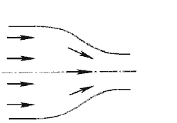
3. sudden narrowing of the channel. In this case, the pressure loss is due to the friction of the flow at the entrance to a narrower pipe and the losses due to vortex formation, which are formed in the annulus around the narrowed part of the flow (Fig. 4.12).

| Rice. 4.12. Sudden narrowing of the tube | 4.13. confuser |
The total pressure loss is determined by the formula;
where the narrowing resistance coefficient is determined by the semi-empirical formula of I.E. Idelchik:
![]()
wherein n \u003d S 1 / S 2- the degree of narrowing.
When a pipe exits a large tank, when it can be assumed that S2/S1= 0, and also in the absence of rounding of the input corner, the drag coefficient ζ narrow = 0,5.
4. Gradual narrowing of the channel. This local resistance is a conical converging tube called confuser(fig.4.13). The flow of liquid in the confuser is accompanied by an increase in velocity and a decrease in pressure. There are only friction losses in the confuser
![]()
where the drag coefficient of the confuser is determined by the formula
![]()
wherein n \u003d S 1 / S 2- the degree of narrowing.
A slight vortex formation and separation of the flow from the wall with simultaneous compression of the flow occurs only at the outlet of the confuser at the junction of the conical pipe with the cylindrical one. By rounding the entrance corner, the head loss at the entrance to the pipe can be significantly reduced. A confuser with smoothly mating cylindrical and conical parts is called nozzle(fig.4.14).
Rice. 4.14. Nozzle
5. Sudden pipe bend (elbow). This type of local resistance (Fig. 4.15) causes significant energy losses, because flow separation and vortex formation occur in it, and the greater the loss, the greater the angle δ. The head loss is calculated by the formula
where ζ count- coefficient of resistance of the knee of a circular cross section, which is determined from the graph depending on the angle of the knee δ (Fig. 4.16).

6. Gradual pipe bend (rounded elbow or elbow). The smoothness of the turn significantly reduces the intensity of vortex formation, and, consequently, the retraction resistance compared to the elbow. This decrease is the greater, the greater the relative radius of curvature of the bend R/d