
The correct device for the finishing floor, what types exist and the differences between them. Types of clean floors and their device
K category: Parquet works
Types of clean floors and their device
Clean floors in residential and civil buildings are arranged with board, parquet from rivets and shields, sheet from hard pressed sheets and carpet from linoleum. In prefabricated construction, the most applicable type of clean floor is that which can be done by industrial methods with minimal labor and Money. At the same time, the floor must be durable and easy to use.
The cheapest construction cost is a plank floor, but it is impractical in operation due to the fact that it often requires repair - rallying and painting.
Parquet and carpet floors have several advantages over hardwood floors. They are strong, durable, beautiful, easy to keep clean and therefore hygienic. The high cost of installing parquet and carpet floors compared to plank floors is offset by durability, low repair and maintenance costs, as well as their high quality.
Along with the usual type-setting and panel parquet made of oak and beech staves, in recent times birch inlaid panel parquet and parquet boards began to be used, which, having the qualities of ordinary parquet, require less labor, speed up work and are cheaper. In addition, floors made of sheet materials - wood-fiber pressed boards - are used on an experimental basis.
Of the carpet floors, linoleum is the most common. The high advantages of linoleum have led to the rapid growth of its production and use in recent years.
The volume of linoleum production in the USSR is planned to be increased in 1958 to 24 million square meters. m per year.
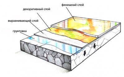
The floor design includes the following elements: coating - the upper element of the floor, which directly serves the purposes of operation;
interlayer - an intermediate layer that connects the coating with the underlying element of the floor or ceiling, or also serves to cover with an elastic bed;
screed - a layer that forms a rigid or dense crust over non-rigid or porous elements of the floor - the underlying layer or ceiling; the screed is also arranged to level the surface of the underlying layer or ceiling, or to give a given slope to the coating;
base - the underlying layer (preparation), or marshmallow, distributing the load on the supporting structure (floor).
The laid floor must meet certain requirements regarding the quality of the materials used and the performance of the work. These requirements are specified in the technical specifications for the production and acceptance of construction and installation works. 1 They contain data on the choice of base, requirements for materials and selection of mastics, determining the dimensions of the structural elements of the floor, the conditions and mode of work, requirements for the quality of the coating. Fulfillment of technical conditions improves the quality of floor coverings and significantly lengthens their service life.
Stacked parquet floors
Type-setting floors, typed or laid from individual thin (15-18 mm thick) staves of hard wood, can have a very diverse pattern (Fig. 1 and 2), created by the location of staves, sometimes different in size and wood species. The most common pattern is the “Christmas tree”, with the laying of one or several rows of parquet-frieze along the walls of the room, separated from the solid parquet by lines-veins, often from a tree of a different, darker-colored breed.
Rice. 1. Types of type-setting parquet: a - green; b - diagonal rows; in - straight rows:: d - straight basket.

Rice. 2. Type-setting parquet with a frieze: a - frieze without edging; 6 - frieze with a ruler; in - a frieze with a vein; g - a frieze with a ruler and a vein; 4 - frieze; 5 - rulers; 3 - veins.
By selecting boards, different in shape, color and layer, a beautiful pattern of an artistic parquet floor is obtained from several types of wood (Fig. 3, a and b).
The type-setting parquet floor is laid on a plank or concrete base.
The plank base is a continuous flooring of boards 35-50 mm thick and 12-14 cm wide, laid with 10-15 mm gaps between them along wooden logs.
A leveling layer of concrete or cement-sand mortar is laid on the thermal and sound insulation layer of loose and non-rigid materials (slag, sand, wood-fiber boards), as well as on lightweight and cellular concrete and prefabricated reinforced concrete slabs. In the presence of waterproofing from rolled materials, the leveling layer is laid from poured asphalt.

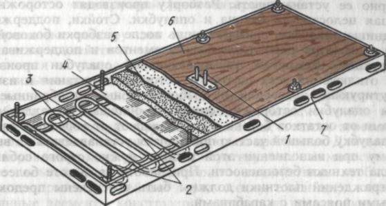
Rice. 4. Type-setting parquet on boardwalk: 1 - parquet; 2 - frieze; .4 - veins; 4 - plinth; 5- cardboard; 6 - boardwalk; 7 - logs; 8 - linings for logs; 9 - reinforced concrete ribbed flooring.
With a wooden base, the rivets are connected to each other with slats made of soft wood inserted into the grooves along the edges of the rivets (Fig. 4). Rivets are attached to the flooring with nails driven through a groove in the edge. With a concrete base, the rivets are laid on hot asphalt or bituminous mastic. In this case, an oblique quarter is selected in the edges of the rivets or the edges are touched with a small (2-2.5 mm) bevel to the base of the riveting (Fig. 5), which is filled with asphalt or mastic during laying.
The quality of type-setting parquet floors and their durability largely depend on the quality of work performed.

Rice. 5. Type-setting parquet on a reinforced concrete floor: a - parquet on asphalt: 1 - parquet; 2 - asphalt; 3 - soundproof layer; 4 - double-hollow reinforced concrete flooring; 5 - fillet; b-parquet on bituminous mastic: 1 - parquet; 2 ~ leveling layer of slag concrete; 3 - only; 4 - soundproof layer; 5~ reinforced concrete flooring.
Weakly strengthened rivets on the rails loosen and creak when walking, rivets loosely glued to the mastic gradually begin to lag behind and fall out.
Panel parquet floors
The foundation (base) of the shield (Fig. 6) is a wooden frame-frame with inserted plank panels. The upper surface of the shield is made rough and parquet boards are glued onto it according to a given pattern (Fig. 7).
Rice. 6. Panel parquet
Rice. 7. Drawings of panel parquet.
Parquet boards (figures) are made in most cases square (squares) with a side equal to 25 cm and a thickness of 7-12 mm. When the squares are oblique with respect to the sides of the shield, the edges of the shield are left unglued; they are filled after laying the shields in place.
The shields are laid on a crate of bars located along beams or floor slabs, and the shields are attached with nails.
Ordinary shields according to OST are made with dimensions of 142X142 cm. In addition, incomplete shields are made - additional ones, laid in cases where full-sized and frieze shields do not fit along the length and width of the room.
The significant complexity of manufacturing and, therefore, the relatively high cost of panel parquet (see Table 2 on page 96), along with higher quality compared to stacked parquet, and more economical use of valuable wood, as well as lower labor intensity of flooring, set the innovators construction sites, the task of simplifying the design of panel parquet and improving the methods of manufacturing and laying panels.
Eng. V. K. Segen, in collaboration with the innovator D. A. Lobzov, developed and mastered the manufacture and installation of parquet boards, which are narrow boards (boards) from a plank base 30-35 mm thick with rivets of typeset parquet glued to it. Unlike the dimensions of standard boards, parquet boards are made 160-180 cm long (according to the dimensions of typical residential sections) and a width equal to the length of the riveting of the most common size (30 cm) or twice the length of short rivets. Parquet boards are produced in two types - ordinary and frieze.
Frieze boards are made in various widths, according to the size of the premises (Fig. 8). Rivets are glued with cement-casein glue of increased strength and moisture resistance.
Laboratory research Institute for Construction showed that, in terms of manufacturing and operation, parquet boards with a base of laths and an even number of squares arranged in a checkerboard pattern are the most effective. The size of the boards in width is 175 and 350 mm and in length - 2100 and 2800 mm with a facing thickness of 6 mm (after cutting).

Rice. 8. Parquet boards: a - general form laying boards; b - ordinary board; c - frieze board; 1 - base; 2 parquet lining; d - construction of the parquet chock of the Institute for Construction
The boards are connected to a tongue or on insert rails (Fig. 8, d and e). To prevent warping of the boards from below, cuts are made along the base.
At construction sites in Moscow, panel parquet based on sheets of dry organic plaster is beginning to be used experimentally. The parquet is glued onto a plaster sheet using hot bituminous mastic (Fig. 9) according to the given pattern. Ordinary shields are cut with an area of \u200b\u200b1 sq. m, and frieze ones - 200 cm long and 30-40 cm wide. Shields are glued to the base of the floor on bituminous mastic. The disadvantages of this parquet are warping of sheets with weak pressing during their manufacture and insufficient strength at the joints with poor fit of joints.
![]()
Rice. 9. Sheet parquet: 1 - parquet flooring; 2 - bituminous layer; 3 - the base of the shield from a solid wood-fiber sheet; 4 - bituminous mastic; 5- soft fiberboard; 6 - reinforced concrete floor.
In Minsk, a new method of laying sheet parquet, called mosaic, with filling the seams between the rivets with xylolite, is being used. The rivets are glued onto a sheet of paper measuring 325X325 mm, following the given pattern. Between the rivets leave gaps of 5 mm. Prepared parquet sheets are glued to the base on bituminous mastic and the joints are filled with xylolite. The advantage of these floors is the absence of gaps at the joints and, at the same time, lower cost compared to conventional type-setting floors.
Rice. 10. Birch inlaid parquet: 1 - birch; 2- bog oak; 3- oak or beech staves.
Carpet and sheet floors
Linoleum floors (cork cemented mass applied to a canvas lining) have a number of positive qualities: they are strong, durable, silent when walking, low thermal conductivity, beautiful, easy to wash and clean and relatively inexpensive. In addition, linoleum has elasticity, which is its good operational quality, but at the same time it requires especially careful preparation of the base surface, as it perceives all the irregularities of the base.
The surface of the wooden base is leveled with careful bulges and filling depressions with putty. A leveling layer of mortar with a thickness of at least 8 mm is applied to concrete surfaces.
Linoleum is used both in one color and printed, having a pattern on the surface (Fig. 11). Linoleum cloths have a length of 3 m, a width - one-color 1 and 2 liters and a printed one - 2 m and a thickness of 2, 3, 4 and 5 mm.
On an experimental basis, rubber linoleum, called relin, is used, which is made from waste rubber and industrial raw materials instead of expensive and scarce materials, such as cork and vegetable oil. The upper finishing layer of relin is made of artificial rubber in one color or with a marble-like coloring with a matte or glossy surface.
Linoleum is glued to the base with mastics; casein and bituminous mastics are used on concrete surfaces, and bituminous resin mastics are used on wooden surfaces.
Along with linoleum, sheet materials are beginning to be used for clean floors: wood-fiber pressed sheets impregnated with resins and painted with resistant paints, as well as laminated plastic tiles. Wood-fiber sheets have a length of up to 2.6 m, a width of 1.2 and 1.6 g and a thickness of 4 mm; tiles with a thickness of 2.5-4 mm have dimensions of 30X30 and 20X20 cm.

Rice. 11. Floor with carpet: 1 - linoleum on mastic; 2 - leveling layer; 3 - reinforced concrete floor panel; 4 - ceiling panel.
Rice. 12 Floor made of solid wood-fiber sheets: 1 - coating; 2 - the basis from a soft plate.
The base for sheet floors is made from sheets of wood-fiber plaster glued on concrete prepared with mastic, or from wooden panels laid on logs (Fig. 12).
The sticker of sheets and tiles is made on cement-breech or bituminous mastic.
Types of clean floors and their device
Every person who decides to make repairs in his apartment, first of all, tries to get acquainted with new technologies and the most popular design solutions. When it comes to floor coverings, polymer self-leveling floors deserve unconditional attention. It cannot be said that the technology for their installation is simple and affordable, but in principle, if you try hard, then do-it-yourself polymer self-leveling floors are a very real development of events.
Polymer flooring is the most unpretentious, but at the same time the most beautiful solution for arranging this part of the room. The name itself indicates that polymaterials are used in their construction. As a rule, they are included in the form of a liquid, which polymerizes during processing. And as a result, the floor surface is smooth and uniform. This type of flooring, produced on an acrylic base, is characterized by a high curing speed.
Important! Due to the rapid polymerization, the floors can be put into service after a short period of time.
Characteristic features of 3d self-leveling floor
The epoxy system has the following advantages:
- High elasticity, due to which the coating is able to withstand strong shock loads.
- impact resistance low temperatures, which allows them to be used in the construction of open marketplaces, the installation of floors in the territory of commercial enterprises of various specializations, as well as when covering floors in freezers.
- Wear resistance, that is, the ability to withstand high mechanical loads for a long period of time.
- No dust emissions.
- Ease and availability of cleaning.
- Resistance to influence of chemical reagents.
- Absolute inertness to various environmental influences.
- High bending strength and comparable compressive strength.
- Unique decorative and aesthetic effect, 3D varnish gives a special effect. The possibility of producing a textured surface and applying a pattern.
Variety of decorative possibilities of 3d floor
Interesting! Polymer floors are characterized by a different composition, where the determining ingredients are such types of resins: polyester, epoxy, polyurethane and methyl methacrylate.
Disadvantages of this technology:
- 3d resin floors are expensive because the component materials are expensive.
- The installation itself is also not cheap, since the application of the topping is carried out in “live” concrete.
- Installation on a new base involves a technological break - at least 28 days.
- Difficulties in the need for repair - to polymer self-leveling floors higher aesthetic requirements. But when performing local repairs, it is very difficult to get into the color scheme - it is almost impossible.
- Vapor resistance.
Polymer self-leveling floors - a suitable solution for a bathroom
Very important! Polymeric decorative floors produced on concrete base, which does not have active waterproofing, after a certain time they will be subject to delamination, that is, delamination. This is due to the rise of groundwater evaporation through the natural capillaries of concrete slabs.
The technology of the self-leveling polymer floor
Foundation preparation
In order for self-leveling polymer floors to serve for a long time and effectively in their production, strict adherence to all technological stages is necessary. In principle, as with the installation of floors from other materials, at the initial stage, due attention is paid to the preparation of the base - and it does not matter whether it is concrete or wood. Although in fairness it should be noted that most often such a coating is applied to a concrete screed.
The base is thoroughly cleaned of debris and dust. All cracks, chips and other defects are sealed. And, in addition, thorough drying is carried out - on an industrial scale, vacuum drying devices are used. In domestic conditions, it is enough to use a heat gun or gas burner. In order to improve the adhesion of the polymer to the base, the base is treated with a primer. In addition, thanks to such protection, all microcracks and pores will be closed, thus, swelling will be avoided during operation.
Polymer application
We emphasize once again: the main defining moment that characterizes polymer floors is technology. It is its unquestioning implementation that will allow you to create ideal polymer floors on your own. So, you need to start applying the polymer composition with a favorable temperature regime in room. If it is cold in it, then it is necessary to heat the air to at least 10 0 C. This is the temperature recommended by most manufacturers of polymeric floor materials known today.
To mix the ingredients, it is better to use a construction mixer or a drill with the right nozzle. The solution must be kneaded very quickly - for everything about everything 2-3 minutes. The thing is, it dries up pretty quickly. The finished mixture is immediately poured onto the base.
Note! In the process of mixing component components polymer coating the release of heat generated as a result of a chemical reaction between them is fixed. For this reason, it is recommended to place the mixing container in a vessel containing cold water bigger size. This will increase the polymerization time of the solution somewhat.
The floor is one of the main parts in the building structure. The floors should not only match the design of the interior of the entire room, but also be characterized by high waterproofing and heat-insulating qualities, coupled with durability and reliability. The technological process of arranging floors, especially floors in a wooden structure, is one of the most costly and time-consuming tasks.
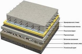
Structural elements of the pie floor
The arrangement of floors is largely determined by the type of flooring that the builders used in the construction of the building.
Base
A fundamentally important part that distributes the load and acts as the main load-bearing element the floor is the base. In wooden or frame-panel buildings erected on pile and strip foundations, on the first floors, the brick columns located directly on the ground become the basis of the floor.
On the second and subsequent floors of the houses, floor beams work as the basis, options with and without lags are possible. In buildings with a monolithic foundation (most often monolithic, stone, brick and block buildings), the floor support, like all floors, including the first, becomes a monolithic concrete slab or a standard reinforced concrete slab.
bedding
As a compensation layer, designed to relieve stresses that appear during thermal expansion, and in winter to compensate for the influence of frost, on the first floors of buildings with a base lying on the ground, bedding is used.
Podsypka significantly improves such technological characteristics of floors as noise and heat insulation. Also, with the help of bedding, the level of the floors is leveled, in cases where the use of other methods is undesirable.
When calculating the thickness of the underlying layer, the load that the structure will have to withstand is taken into account.
The nature of the load level directly affects the choice of materials used for backfilling. The range of materials for backfilling is quite wide: different types sand, expanded clay, clay, crushed stone, small stone, slag, gravel, even in some cases specially processed sawdust.
Screed and subfloor
These floor elements serve to level the surface before laying the floor itself, and if necessary, are able to create a surface with the required slope.
Draft floors, depending on the building materials used, are divided into prefabricated and monolithic. A monolithic subfloor is made to us on the basis of various concretes, cement-sand mortar, polymeric floors of cement fiberboards.
Prefabricated floors are mounted from plywood sheets, boards, chipboard, fiberboard, OSB, gypsum fiber sheets. Today, the so-called dry screeds from GVLV (sheets or slabs of moisture-resistant gypsum fiber) are becoming more and more popular.
Interlayer
Interlayer is an intermediate layer that connects the finished floor covering to the underlying layer of the floor pie. It also acts as a shock-absorbing bed.
Layers, depending on the functions they perform, can be of 2 types:
- The bonding layer unites the coating with the base due to the adhesive force. These are such layers as: mastics, putties, adhesives, concretes, various solutions. They can be presented as a dry mix, simple components, suspensions, solutions, liquids, one-component and two-component formulations, and so on. Liquid glass, polymers, resins, cement, bitumen and other substances are in this case the binder components.
- The layer, which is the elastic compensator of the underlying floor, evenly distributes the load on the load-bearing parts of the finished floor covering. When used as a topcoat for laminate boards, solid and parquet board this layer is a substrate of polymers.
Waterproofing, vapor barrier and noise-absorbing insulation layers
Waterproofing, vapor barrier, sound insulation, thermal insulation is used to protect the floor structure from any impact.
The waterproofing layer protects the floor from seepage from the ground of subsoil water and other liquids, including chemically aggressive ones. This layer also stops the capillary rise of ground moisture.
Sheet or roll materials are used as insulation - hydroisol, polyisobutylene, roofing material, only leather, as well as crushed stone soaked in tar or bitumen, or just asphalt concrete.
The vapor barrier protects against diffusion penetration into the insulation of condensing vapors that occur during the life of people living in the premises of the building.
The heat-insulating layer also serves as sound insulation. This insulation layer is assembled from board or mat materials such as extruded polystyrene foam, mineral wool, glass wool. It is also possible to use polymers by foaming them directly on site.
Floor covering
The final coating of floors, it is subject to all operational loads. The division into types of coatings is based on the characteristics of the materials used. Coatings are: monolithic (they are also called solid), rolled, sheet and consisting of individual elements.
The arrangement of floors, the choice of finishing coating for them should be based on the nature of the use of the premises. In living rooms, linoleum, plank, parquet or laminate floorings are traditionally laid.
In bathrooms, showers, bathrooms or in the kitchen, linoleum is used or ceramic tiles are laid. For dry rooms such as utility rooms, pantries, the use of flooring from plywood sheets, chipboard, OSB, fiberboard is quite justified.
Arrangement of draft floors of a country house and a summer residence
Most often country houses build from wood. This means that the floors of the floors in such a house will only be wooden, since such a house is not designed to withstand the loads of monolithic concrete or standard reinforced concrete structures.
 The device of floors before assembling the finish coating on the beams involves the creation of a subfloor.
Its assembly is carried out directly on the beam ceiling with a small distance between the beams, otherwise (if the step is too large) additional logs from the beam are attached to the beams.
For subflooring, you can use an unedged board, its optimal thickness is from 15 to 50 mm. This is usually lumber of lower grades of softwood, but not so necessarily, cheaper hardwood can also be used.
When installing the base floor, the boards are usually not nailed, but the so-called tongues (grooves in the floor beams), “cranial” bars or “skulls” or shoulders are used.
The main purpose of the draft floors in a wooden building:
- creation of the necessary frame for the rigidity of the floors themselves and additional for the entire wooden structure;
- acts as part of the supporting structure for laying protective materials and the final floor covering;
- the formation of an air gap that retains thermal energy.
Subfloor equipment protects the structure country house from deformations and distortions during further enhanced operation.
Over time, the walls of a wooden summer cottage can shrink, which subsequently causes the base floor to shift, but the finish coating will not be broken and will remain in the same place, therefore floor coverings in private wooden house able to serve for decades.
In addition to boards, it is possible to use OSB or chipboard for laying the base floors.
Materials for arranging the finishing floor
Chipboard
Chipboard (stands for particle board) is made from compressed wood chips, binders and additives.
Chipboard production technology involves 2 stages:
- Mixing wood shavings with a water-repellent additive (paraffin emulsion is most often used) and urea-formaldehyde resin.
- Flat hot pressing of the mass obtained in the first stage.
Chipboard is produced in 3 types: P1, P2, P3.
For the construction of floors, the P-3 brand is preferred, since it is the thickest. Chipboard boards should have even, regular 90° angles and the edges should be cut smoothly. The deformation measured along the diagonal of the slab should not exceed the standard 1mm per 1m of length.
OSB
The abbreviation stands for Oriented Strand Board, which translates as Oriented Strand Board. It is made using environmentally friendly technologies. OSB also has good fire resistance indicators, which plays an important role for wooden houses. Plates, according to the requirements of resistance to fire, with a thickness above 1.8 cm have class 3, and up to 1.8 cm - class 4 resistance.
The main difference between OSB is that it is pressed from long wood chips, directed perpendicular to each other.
For the manufacture of OSB, coniferous wood is used. The chips going to production should be about 18 cm long, while its thickness will be 0.5 - 0.9 mm and a width of 6-40 mm. As you can see, the ratio of width and length varies within the proportions from 1:3 to 1:6.

The chips are knitted with resins, subjected to high pressure and high temperature. Also, artificial wax is added to the OSB composition, which increases the quality of the material, and boric salts, which give the plate protective characteristics.
The binders in the manufacture of OSB are most often phenol-formaldehyde and urea-melamine resins and isocyanate esters.
Thanks to another useful feature - the strength of OSB boards, you can drive nails into them, stepping back from the edge of only 1 cm, and at the same time it will not break.
Along the perimeter of the slab, the gap between nails or self-tapping screws should be at least 15 cm, and 30 cm will be enough for a step in the internal space. OSB can also be fixed using special wood glue, or simply PVA.
Linoleum
Natural linoleum and PVC coatings are materials that are completely different in nature, but out of habit they are called the same.
Real linoleum is a coating made only from natural ingredients. For its manufacture, wood resin, flax oil, limestone, cork (ground to a state of flour), a variety of pigments and jute fabric as a base are used.
Linoleum is produced in panels 2 or 4 meters wide, but its thickness varies from 2 to 4 mm. Due to the presence of bactericidal qualities, real linoleum is widely used in educational, preschool and health care institutions.
In addition, the coating surface has good antistatic properties. There is also the production of special acoustic and conductive types of this coating.
Also, this material is resistant to fats and solvents, but at the same time it does not tolerate the effects of alkalis. Linoleum has 6 lightfastness units.
Over time, the coating may change color, this is due to the drying of linseed oil. But under the influence of ultraviolet rays, the color is gradually restored. In connection with this cutting, the material must be made only in one room, otherwise, due to different light intensity, parts of the coating will initially acquire a different shade.
Linoleums made from natural ingredients vary from class 21 to class 34 in terms of wear resistance, depending on the thickness of the coating, according to EN No. 429.
Polyvinyl chloride is a primary element for the manufacture of artificial linoleum. According to the degree of wear resistance, it is divided into semi-commercial, commercial and household.
Their classification is directly dependent on the scope and intensity of use. According to the EN 685 standard, PVC coatings occupy from 21 to 42 classes.
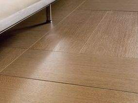
Parquet and parquet board
Parquet floors are highly wear resistant, durable, retain heat well and have good sound insulation. The coating is highly aesthetic and will perfectly fit into any interior.
For the manufacture of parquet, both types of wood familiar to us (beech, birch, ash, oak, walnut) and exotic ones (wenge, merbau, kempas, manila and others) are used.
One of the main characteristics of wood used for parquet is hardness. The harder the wood, the more durable and stronger it is. There are two main scales of hardness. The first scale originates from the hardness index for oak (100 units). Accordingly, the remaining grades have a designation of hardness relative to it. The second (Brinell scale) complies with EN 1534:2000.
In the manufacture of parquet, three types of material sawing are used: tangential, radial and mixed.
The structure of the material obtained by radial sawing is homogeneous. This is achieved by the fact that during radial sawing of the trunk, the cut goes across the annual rings.
Such a material, in comparison with the material obtained by tangential sawing, has a significantly lower coefficient of linear expansion, and therefore it has a greater resistance to negative influences.
Since the exit finished products from an equal volume of wood, it is lower in comparison with other types of sawing, then the resulting radial parquet is, accordingly, more expensive.
When sawing material tangentially, the cut runs tangentially to the annual rings of the wood, thanks to which the surface of the dies flaunts their “arched” pattern.
At mixed type parquet combines both radial and tangential patterns. For the production of such parquet, the central part of the trunk is used, with the exception of the core.
The classification of parquet by grades is based on several features: the presence and number of defects (sapwood, knots, and others), as well as the color, shades and texture of the material. The most famous are the varieties "rustic", "natural" and "standard".
Laminate
Modern technologies have made it possible to create coatings with a different image. Therefore, the pattern of texture on the surface of the laminate can imitate stone, wood, cork and other natural materials.
The imitation of an old tree is the most widespread, as well as a full 3D imitation of any kind of wood with an accurate reproduction of its texture pattern. Leading manufacturers produce skirting boards, sockets, profiles, which are combined with the entire floor in terms of color.
Laminate production technology is a process of gluing various materials under high pressure. Manufacturers each use their own technology and their own set of raw materials.
But for all brands of laminate, four layers remain common:
- the foundation;
- stabilizing (resisting deformation);
- decorative (carrying the image);
- upper protective;
Many species have various additional layers.
One of the tasks of the protective component of the upper layer is to provide the material with thermal stability, wear resistance (especially valuable when used in the country), resistance to light.
For the manufacture of this layer, various additives are used (for example, the second hardest mineral is corundum) and melamine resins.
Some companies use another protective transparent layer, which is created from symmetrical aluminum dioxide particles, to increase the strength of the material.
Melamine resin impregnated paper is the basis for the decorative finish of laminate flooring. This component is UV resistant.
The base is made from fiberboard, occasionally from chipboard. Fiberboard is used only with medium or high (MDF or HDF) density. For MDF, this figure is 650/850 kg/m 2 , for HDF it is higher than 850 kg/m 2 .
Of course, the higher the density of the base of the material, the greater its technical properties: bending strength, wear resistance, water resistance, impact resistance.
The last, stabilization layer, performs compensation functions. With changes in microclimate conditions (changes in temperature and humidity), it prevents the laminated coating from shifting.
This layer is created from waxed thick paper or from an analogue impregnated with melamine resins. Various locking systems are used to fix the floor panels without glue. The most common fiber and aluminum construction locks. The fiber-type lock is located in the fiberboard layer and is a tongue/groove system.
Aluminum lock systems are similar in structure to fiber locks. But they are produced separately from the laminate, and when laying it is necessary to fix them to the panels. Accordingly, it takes more time to install laminate flooring with aluminum locks than a laminate floor with fiber locks.
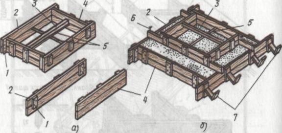
Formwork should be installed on a solid foundation. It cannot be installed on frozen ground, since when the ground thaws, the formwork will sag and change its shape. Opa type selection
Rice. 171. Formwork of strip foundations:
a- rectangular height up to 200 mm, b - the same, 200 ... 500 mm, in- rectangular stepped height up to 750 mm, G- fixing the guide board, d- wooden clamp (detail), e- steel clamp (detail); 1 - spacer, 2 - stakes, 3 - side shield or side board, 4 - clamping boards, 5 - struts, b - clamps, 7 - guide
splints for the construction of concrete and reinforced concrete structures depends on the following data: the nature of the structures, the size of the spans, the height and length of the structures, the height of the structures from the ground level, etc.
The design of the formwork should be such that it can be easily assembled and disassembled without causing damage to concrete products and difficulties in installing reinforcement, laying and compacting the concrete mixture.
In construction, mainly collapsible formwork is used (Fig. 171), which is assembled from prefabricated elements - tsndts, boxes, removed from molded products after the concrete has reached strength that allows stripping. For the manufacture of formwork, small, large and unified panels are used. To absorb lateral pressure from the freshly laid concrete mix, internal fasteners are made of wire ties connecting opposite formwork walls.
In all formwork panels, the sides adjacent to the concrete
Rice. 172. Formwork of foundations for columns:
a- rectangular, b- stepped; / - thrust bar, 2 - covering shield, 3 - spacer, 4 - mortgage shield, 5 - wire tie 6 - mounting nail, 7 -
must be smoothly processed. There are two ways to install the formwork: before the installation of the box, reinforcement is placed in the form of rigid welded frames, or the formwork is mounted before the installation of the reinforcement.
Prior to the installation of the formwork, a geodetic breakdown of the axes and fixing the marks of the buildings under construction are carried out.
For tape rectangular foundations (Fig. 171, a), formwork up to 200 mm high is made of boards 40 ... 50 mm thick. On the inside, the boards are fixed to the desired size with spacers, and on the outside, with stakes driven into the ground close to the boards, which also perceive the lateral pressure of the concrete mixture. The formwork of strip foundations (rectangular), having a height of more than 200 mm, is made of shields (Fig. 171.6). The position of the shields is fixed on the inside with spacers made of bars with a section 50X 50 mm, and from the outside - a device of pressure boards, struts and stakes. The lateral pressure of the concrete mixture is perceived by these devices.
For the formwork of tape rectangular stepped foundations with a height of 500 ... 750 mm, shields with clamps made of boards or metal corners are used (Fig. 171, c).
The width of the panels should be equal to the height of the foundation, the internal size of the formwork - the width of the foundation. This size is set along the cords stretched along the bottom of the trench. The foundation shields are fixed from the inside with struts, and from the outside - with clamps. Outside, the shields can also be fixed with struts, stakes or struts that rest against the walls of the trench.
Installation of formwork for strip foundations up to 750 mm high begins with the installation of guide boards, which are fastened with stakes driven into the ground. After fixing the guide boards and verifying the correctness of their installation on them with one hundred-260

Rice. 173. Formwork of rectangular columns:
a- assembled box, b - steel clamp, in- fastening of the column box
struts (flares); / - door, 2 - box, 3 - cutouts for formwork entry
beams, 4 - clamps, 5 - wedges, b - base frame, 7 - holes for wedges,
8,9 - shields, 10 - thrust bars 11 - frame, 12 - cork, 13 - brace
the crowns of the foundation put up shields. The plane of the shields must coincide with the edge of the board. In a vertical position, the shields are fixed with braces. Then they put the shields on the other side of the foundation, strictly observing the internal dimensions and fixing them in the design position with spacers, after which they are fixed with temporary spacers or clamps.
The formwork of rectangular and stepped foundations for columns (Fig. 172) is assembled from two types of shields - covering and embedded. The position of the shields from the inside in the design position is fixed with a spacer and a wire tie, and outside - with stakes driven into the ground.
The formwork of the foundations for the columns is installed as follows. Jointed slats are temporarily sewn over the box and the axis of the column is found along them. When installing formwork for a rectangular foundation, the position of the box is determined by weights,
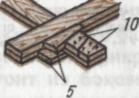
Rice. 174. Installing the formwork of beams and girders:
a- general view of the installation, b - cross section of the box in the presence of a plate, in- I the same, without a plate; 1 - the bottom of the run box, 2 - side panels of the run box, 3 - ■ side shields of the beam box, 4 - the bottom of the beam box, 5 - stand, 6 - rack head, 7 - pressure boards, 8 - slab formwork board, 9 - podkruzhnaya board, 10 - contractions, // - screeds
lowered from the wire axles, while the weighty cords should touch the planed rails. After installing and aligning the box in the design position and fixing it with stakes driven into the ground, the temporary rails are removed.
The formwork of rectangular columns (Fig. 173) is assembled from two pairs of shields on nails. The width of one pair of shields (embedded) is equal to the width of one of the sides of the column, and the width of the other pair of shields (covering) is equal to the width of the other side of the column with the addition of double the thickness of the board. From the outside, the shields are fastened with steel or wooden clamps, which perceive the lateral pressure of the concrete mixture and the forces from vibration during its compaction. Clamps are installed after installing the box.
The formwork of the columns is installed as follows. First, on the foundation (podkolonnik) mark the axis of the columns. In the process of concreting, wooden plugs are laid in the foundations. After marking the axes of the columns, a base frame is placed on the foundation so that its axes coincide with the axes of the column drawn on the foundation; after that, the shields of the column are brought to the foundation and they begin to assemble the box, installing it in a frame.
After installing the box, check the accuracy of the internal dimensions, the coincidence of the axes of the reinforcement of the column with the axes of the formwork, the verticality of the installation of the formwork. Clamps on the box put after us-
tanovki and reconciliation formwork. The assembled boxes, installed in frames, in the design position with a column height of up to 6 m, are fixed with flares.
The formwork of beams and girders (Fig. 174) is usually installed at the same time and is made in the form of boxes with a bottom from previously knocked together shields. The box must fit snugly against the bottom, otherwise laitance will flow out of the concrete mixture through the cracks formed. When assembling formwork at a height of more than 6 m, scaffolds are used, and when assembling formwork at a height of less than 6 m, scaffolds are used.
At a height of less than 6 m, the formwork is installed as follows. First, the bottoms of the purlin boxes are installed in the cutouts of the column boxes and fixed after leveling with mounting nails. After that, logs are laid on the ground and inventory racks are placed on them at the right distance, which are brought under the bottom of the runs. The verticality of the installation of the racks is checked by a plumb line with wedges. Racks are fixed with mounting nails through the bottom into their heads. The side shields of the purlin box are attached to the sides of the cutouts of the column boxes with pressure boards, attaching them with nails to the head of the rack. Upon completion of these works, the bottom of the formwork is inserted into the cutouts of the boxes of columns and girders, bringing racks under it, and side panels are placed.
The joints of the beam boxes with the purlin boxes are sealed with beveled rails, attaching them with mounting nails. The box of the beam consists of side shields, a bottom, bouts, a subcircle board is located on the side of the shields. To obtain the desired dimensions, the box is pulled together by contractions.
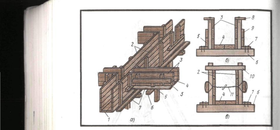
The wall formwork (Fig. 175) consists of two strictly parallel panels assembled from panels. The distance between the panels should be equal to the design wall thickness. When assembling the formwork, the wall thickness is fixed with temporary spacers.
First, they plan the base on which the formwork will be assembled, after which the guide boards are installed. In the design position, the guide boards are fixed with pegs driven into the ground. If the guide boards are placed on a concrete base, then they are fixed with nails, forgotten in corks, previously laid in concrete. The edges of the guide boards facing the concrete are milled. For walls up to 500 mm thick, the formwork is assembled from panels supported by ribs, and for walls more than 500 mm thick, the panels are additionally fastened with contractions. The lateral pressure of the concrete mixture is taken up by twisting or tie bolts. Coupling bolts are lubricated with mineral oil before installation so that they can be easily removed. As the concrete mixture fills the spaces between the panels, the temporary spacers are removed. When installing the wall formwork, it is necessary to check the verticality of the installed panels with a plumb line, and with a template - the distance between the panels.
Thermosetting formwork panels are also used on the os-
Rice. 175. Wall formwork:
a- guide board installed on the ground, b- the same for concrete preparation, in- general view of the wall formwork, G- a rib assembled from two boards; / - guide board, 2 - peg, 3 - cork, 4 - Wall shield, 5 - edge, 6 - temporary spacer, 7 - wire twist, S - fight, 9 - hollow concrete bar
new collapsible formwork "Monolith-72", using which, along with the formation, it is possible to perform heat treatment of freshly laid concrete mix (electric heating). The formwork shield (Fig. 176) is arranged as follows: clamps made of wire with a diameter of 3 mm are welded on the inner surface of the steel deck, to which electric heaters are attached.
A bracket with a fork connector is bolted to the middle transverse edge of the shield, to which the ends of the electric heaters are connected. A reflective screen made of thin aluminum is placed above the electric heaters at a distance of 10 ... 15 mm, designed to reduce heat loss. The internal gaps of the shield are filled with insulation. On top of the insulation (shla-264
Rice. 176. Shuttering board with thermosetting structure heating
TsNIIOMTP:
/ - male connector, 2 - electric heater, 3 - clamps, 4 - reflective screen, 5 - insulation, 6 - protective plywood cover with waterproof coating,
7 - shield frame
felt plates) to protect it from damage, put plywood 4 ... 5 mm thick.
The formwork is supplied with electricity from step-down transformers through inventory switchgears. The formwork is installed on the ground, cleared of debris, snow, ice and preheated. Approximately half an hour before filling the formwork with concrete, turn on the electric heaters. Shield dimensions 500...600X 1200... 1800 mm.
The stability of the formwork during installation is ensured by the posts, which rest on a solid foundation and are fastened with expansion screws. In no case should the formwork be allowed to sag, bulge, i.e. deform during concreting. The site for the installation of the formwork must be flat, without bumps and depressions. When installing shields, it is necessary to monitor the density of their adjoining to each other. Before the reinforcement is laid, the formwork is inspected and the formwork surfaces and their position relative to the design axes of the structures, the correct installation, fixing of the formwork and the installation of plugs, embedded parts, the tightness of the connection of panels and joints are checked.
The correctness of the dimensions of the formwork is checked with a steel meter, the horizontalness - with a level, the verticality of the boxes, columns - with a plumb line. The finished formwork is accepted by the master or foreman.
Before installation, the formwork is cleaned of debris, dirt, reinforcement - from rust, the existing gaps in the formwork are sealed. The surfaces of the formwork to be wrapped are lubricated.
The formwork is dismantled after the concrete reaches the required
strength with the permission of the foreman, those workers who will re-install it. Disassembly is carried out carefully, without violating the integrity of concrete and formwork. Racks supporting the bottom of the formwork are removed only after dismantling the side formwork and inspecting the stripped elements and supporting structures. The dismantling of the thermosetting formwork is carried out after disconnecting all the panels from the power sources and removing the switching wiring from the working area. The dismantled formwork elements are carefully removed, cleaned with metal brushes from the remnants of concrete and freed from protruding nails.
For the most part, the formwork has to be installed at a height, therefore, when performing this work, safety regulations must be strictly observed. When working at a height of more than 1.5 m without fences, carpenters must be provided with safety belts with carabiners.
Permissible deviations of the positions and dimensions of the installed formwork, supporting scaffolding from the project are as follows (mm):
The distance between the supports of the flexible formwork elements and the distance between the braces of the vertical supporting structures from the design dimensions:
per 1 m length 25
for the entire span, no more than 75
Distance from the vertical or the design slope of the formwork planes and the line of their intersection:
per 1 m height 5
full height:
foundations 20
walls and columns up to 5 m high 10
walls and columns over 5m high 15
beams and arches 5
Displacement of the formwork axes from the design position:
foundations 15
walls and columns 8
beams, purlins, arches 10
The internal dimensions of the formwork of beams, columns and the distance between the internal surfaces of the wall formwork from the design
sizes 3
Local irregularities of the formwork when checking a two-meter
Work on the erection of formwork on one vertical on two tiers is permitted only with the installation of canopies that protect workers working below. Open openings in the walls, located at the same level, with the ceiling, on which the formwork is being installed, must be fenced. Boards, boards should be laid so that the tips of the nails are facing down. Formwork can be dismantled with the permission of the foreman, foreman, and formwork for structures longer than 6 m - with the permission of the chief engineer of the organization. When dismantling the formwork, it is necessary to take measures against the possible fall of the formwork elements.
Floors belong to the category of the main elements of the building, which determine the thermal comfort of the premises, their hygiene, aesthetics and reliability. The device of the bases under the floors is carried out directly on the ground or on the floor. The service life, convenience and practicality of the exploited floor covering will depend on how the floor is made from the very beginning to the finish coating.
There are many options that differ in the technology of creation.
What should be the gender: general provisions
According to SNiP floor device, its multilayer structure mainly includes the following layers.
- The coating, in other words, the “clean floor” is the top one, which is directly under the influence of operational loads.
- Interlayer or intermediate layer - acts as a link between the coating and the underlying layer or serves as an elastic "cushion" for coatings.
- The base for the coating or screed - levels the plane of the ceiling / underlying, gives the coating a given slope, covers the pipes of various communications.
- Waterproofing is protection against the penetration of groundwater, sewage or other liquid.
- Underlying - "distributor" of the load on the ground. For rooms located above an unheated underground, a heat-insulating layer is arranged.
The technological map is compiled individually, taking into account the specifics of the location, base, floor material, purpose of the room, etc.
Floors are subject to specific regulatory requirements, which are determined by the purpose of the building, the processes taking place in the room.
So, materials and design should provide it:
- strength, i.e. resistance to external influences, say, abrasion, impact resistance, etc.;
- low thermal conductivity;
- good sound and;
- noiselessness and non-slip;
- be fireproof in fire-hazardous rooms, waterproof and water-resistant in wet rooms, etc.
As a rule, laying of the floor covering is started upon completion of construction, installation and finishing works, during which the coatings can become wet and dirty. It is clear that the type of floor is selected based on the requirements most relevant in each specific case, and proceeding from this, they carry out .
Flooring options by base type
Ground for floors
Often under walls country houses and frameless buildings lay strip foundations. Finely recessed tape or a full-fledged foundation of this type should lie lower than the freezing depth level. Gender on strip foundation are performed according to two main technologies, which in the future may differ in the method of execution. The most budgetary and least time-consuming option is considered to be the floor on wooden beams.
It is also possible to use steel beams, but this can greatly affect the cost of execution.
Such a floor has certain disadvantages. Much more reliable, although the most expensive, is the flood type, equipped with waterproofing and insulation.
It must be leveled according to the marks provided for in the project, and the soil is carefully compacted - it is important that it is thawed.
 It is impossible to use vegetable soils, as well as natural and bulk soils without their preliminary compaction. When laying such materials, the possibility of subsidence and heaving of the structure should be excluded.
Before laying the underlying concrete floor, the non-rock base from the soil is preliminarily strengthened: fragments of crushed stone or gravel 40–60 mm in size are scattered over its surface and drowned in slightly moistened soil to a depth of about 40 mm.
When arranging the base on the floor, it is necessary to carefully seal the gaps, mounting holes, as well as the places where the floors are adjacent to walls or partitions.
The underlying layer is made in two versions:
- hard - made of concrete, class from B22.5;
- non-rigid - from gravel, crushed stone, sand, slag, expanded clay, etc. with a mandatory mechanical seal.
Requirements for laying concrete floor
If there is a possibility that during operation the floor may be exposed to aggressive liquids, organic solvents, water, oils and emulsions. The base must be rigid. The thickness is at least 10 cm, and if it also serves as a coating, then the thickness is increased by 2–3 cm compared to the calculated one.
In rooms where temperature differences are expected during operation, expansion joints must be provided on the base, mutually perpendicular and with a step of 6–8 m. Moreover, they must correspond to the expansion joints of the building, and in floors with a slope for drainage - with a watershed floor.
The height difference on the rigid sub-base over a length of 2 m should not be greater than:
- 5 mm - under the coating on a layer of bituminous mastic or when performing pasting waterproofing;
- 10 mm - for a different type of coating.
In the case of a non-rigid layer, the parameters are already different:
- layer thickness: 6 cm - for sand, 8 cm - for gravel, slag and crushed stone;
- height difference - 15 mm.
waterproofing layer
 Waterproofing protects against the penetration of all kinds of liquids (medium and high intensity) in the floors on;
- overlap - water, neutral solutions, organic solvents, mineral oils and emulsions thereof, acids, alkalis and their solutions, as well as substances of animal origin;
- soil - water, neutral solutions, acids, alkalis and their solutions and substances of animal origin.
The waterproofing material in the floor structure is laid continuously with a rise of at least 30 cm on the walls and at all points of contact with structures protruding above the floor.
Waterproofing is provided under the underlying layer of concrete, if it is located in an area where capillary rise of water from the soil is possible. Lifting is considered dangerous if it reaches:
- 0.5 m - sand base, fine and medium size;
- 0.3 m - from coarse sand;
- 2.0 m - loam, sandy loam, clay;
- lower than the level of revenge of the building;
- with medium and large exposure to the floor of solutions of certain acids: sulfuric, nitric, acetic, hydrochloric, phosphoric, chromic and hypochlorous.
Sound and heat insulating
The thermal insulation layer is provided:
- in floors with normalized heat absorption;
- floors on the ground, if they are located higher than the blind area of the building or lower than it by half a meter;
- on floors that are located above arches, basements, unheated rooms;
- in areas where the floor adjoins the walls, which separate the heated room from the unheated, or outdoor.
The thickness of the sound and heat insulation layer is set according to SNIP II, respectively, 12–77 and 3–79.
Screed
A screed is necessary in cases where required should be provided when necessary:
- level the surface of the layer below;
- distribute the load over the sound and heat-insulating layers;
- ensure semi-normalized heat absorption;
- cover the pipeline;
- create a slope on the floors arranged on the ceilings.
The thickness of the screed when creating a slope at the junction points to channels, ladders and sewer trays is:
- at least 20 mm - laying on floor slabs;
- 40 mm - along the sound or heat insulating layer;
- to cover communication pipes, the thickness of the screed should be 1.5–2.0 cm greater than their diameter.
Screeds are monolithic and prefabricated. The latter are primarily distinguished by short deadlines for the execution of work and the complete absence of any wet processes.
Bulk floor device

The pie of the bulk floor construction with a “dry screed” includes:
- vapor barrier, which is laid on the ceiling. The vapor barrier of the floor is necessary to protect the backfill located on top of it from moisture. There are several reasons for getting wet;
- the penetration of moist air from the premises located on the lower floor;
- moisture released from concrete structures, due to capillary suction from the walls;
- excess water in a mixture made for monolithic overlap.
- dry backfill - for this, highly porous bulk materials with an optimal granular composition are used, this ensures minimal sedimentation. They should have a mineral base and low hygroscopicity.
- "Dry screed" bulk floor - usually mounted from or gypsum sheets. In addition to sheet materials, plate materials are also used, for example, OSB, chipboard, ADC, CSP boards.
Safety
When carrying out work, they are guided, in particular, by SNiP on "Safety in Construction" and "Fire Safety".
Workers need to be trained in working methods and familiarized with the rules relating to safety, instruct about the flammability of a particular material, as well as fire safety measures.
To work with construction machinery, electrical and mechanized equipment, persons with the appropriate qualifications, not lower than I I qualification group, are allowed.
The equipment must be fully functional, the handles must be securely fastened, there must be no breaks in the wires of the electrical equipment, they must not intersect with other live wires, the electric cable must be in good condition, and the equipment case must be grounded.
For a number of works, for example, mosaic, rubber shoes and rubber gloves are needed.
Abrasive wheels of grinding machines must be firmly fixed and protected with a safety shield.
When working with adhesives, forced ventilation must be provided. In extreme cases, work is carried out with open windows, vents and doors for ventilation. It is forbidden to smoke and carry out gas welding in these rooms. In them and in the corridors it is necessary to post inscriptions: "It is flammable!". "Do not smoke!".