
Pneumatic drive of the brake system. General information about hydraulic and pneumatic drives
The initial energy in pneumatic drives is the energy of compressed air. The pneumatic actuator is widely used in fixtures due to its speed (acting speed - fractions of a second), simplicity of design, ease and simplicity of control, reliability and stability in operation. At the same time, the pneumatic actuator has disadvantages - uneven movement of the rod, low air pressure and noise when exhaust air is released.
The pneumatic drive includes the following parts: a source of compressed air - usually a workshop or factory compressor unit; power unit - a pneumatic motor that converts the energy of compressed air into force W on the rod; pneumatic equipment - control devices, distribution, safety devices, etc.; air ducts.
The pneumatic motor is arranged in one design with the device. The rest of the devices are placed outside the device, with the help of air ducts they are connected to the device.
Pneumatic motors are three types- piston (pneumatic cylinders, Fig. 2.59, a), diaphragm (pneumatic chambers, Fig. 2.59, b) and bellows (Fig. 2.59, c).
Rice. 2.59. Types of air motors
Pneumochambers are a structure of two cast or stamped cups, between which an elastic diaphragm made of steel or rubberized fabric is clamped. The working cavity of the bellows motor is a corrugated closed chamber 1 made of thin-sheet corrosion-resistant steel, brass or phosphor bronze, elastically expanding in the direction of the stroke of the rod 2 under the action of compressed air. The reverse stroke is carried out when air is supplied inside the chamber 3. The working stroke of the pneumatic chamber rod and the bellows is therefore limited by the magnitude of the possible elastic deformation, while for the pneumatic cylinder it can be any. The pneumatic cylinder for sealing working cavities requires seals on the piston and rod, which wear out rather quickly (usually their service life does not exceed 10 thousand cycles), diaphragms are more durable - up to 600 thousand cycles. The bellows do not require any seals.
Seals are critical structural elements of air motors. They are required in the annular gaps between the piston and cylinder, rod and cover, and in fixed joints where air leakage is possible. In modern pneumatic motors, two types of seals are used (Fig. 2.59, a): 1 - V-shaped cuffs made of oil-resistant rubber according to GOST 6969-54 for sealing pistons and rods, 2 - O-rings made of oil-resistant rubber according to GOST 9833-73 for seals for pistons, rods and fixed joints.
In addition, original multi-seat devices with tubular diaphragms are used. The ends of the tubes are closed with plugs and a fitting for supplying compressed air is screwed into one of the plugs. When compressed air is admitted, diaphragm 3 (Fig. 2.60, a) expands, compresses springs 2 and moves plungers 1, clamping parts. When the air is released, the plungers return to their original position under the action of the springs.
n1.docx
1. Pneumatic actuators. Pneumatic cylinders, rotary and turbine pneumatic motors.Pneumaticdevice- called a device in which compressed gas is used as a working fluid, physical properties gases are manifested in the form of pressure on the surface of the solid links of the device or in the form of aerodynamic effects.
Pneumatic drive is a system of interconnected pneumatic devices designed to set in motion the working bodies of machines or working links of mechanisms. Pneumatic devices in drives can be interconnected by pneumatic lines (pipelines) and mechanisms (articulated lever, gear, cam, etc.).
Executive devices are designed to convert the energy of compressed air into the energy of the movement of the working bodies of the machine.
The most widespread volumetric pneumatic motors (piston, rotary and chamber (balloon)).
The pneumatic motor is used to drive various tools (drills, wrenches, jackhammers, grinding heads), ensuring the safety of work in explosive places (with accumulation of gas, coal dust), in an environment with a high moisture content.
2.Basic elements and diagrams of pneumatic actuators.
Pneumatic drive - a set of devices designed to set machines and mechanisms in motion by means of compressed air energy. Mandatory elements of the pneumatic actuator are a compressor (pneumatic energy generator) and air motor .
The main purpose of the pneumatic drive, as well as mechanical transmission, is the transformation of the mechanical characteristics of the drive motor in accordance with the requirements of the load (transformation of the type of movement of the output link of the engine, its parameters, as well as regulation, overload protection, etc.).
In general terms, the energy transfer in a pneumatic actuator occurs as follows:
The drive motor transmits torque to the compressor shaft, which supplies energy to the working gas.
The working gas after special preparation through pneumatic lines through the control equipment enters the air motor where pneumatic energy is converted into mechanical energy.
After that, the working gas is released into the environment, in contrast to the hydraulic drive, in which working fluid through the hydraulic lines it returns either to the hydraulic tank or directly to the pump.
Typical diagram of a pneumatic actuator
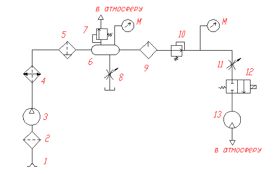
Typical scheme of pneumatic drive: 1 - air intake; 2 - filter; 3 - compressor; 4 - heat exchanger (refrigerator); 5 - dehumidifier; 6 - air collector (receiver); 7- safety valve; 8- Throttle; 9 - oil sprayer ; 10 - pressure reducing valve; 11 - throttle; 12 - distributor; 13 pneumomotor; M - manometer.
Air enters the pneumatic system through air intake .
The filter cleans the air in order to prevent damage to the drive elements and reduce their wear. The compressor compresses the air.
Since, according to Charles' law, the air compressed in the compressor has high temperature, then before air is supplied to consumers (usually air motors), the air is cooled in a heat exchanger (in a refrigerator). To prevent icing of air motors due to air expansion in them, and also to reduce corrosion of parts, a dehumidifier.The air collector serves to create a supply of compressed air, as well as to smooth out pressure pulsations in the pneumatic system. These pulsations are due to the principle of operation of volumetric compressors (for example, reciprocating), which supply air to the system in batches. oil dispenser lubrication is added to the compressed air, which reduces friction between the moving parts of the pneumatic drive and prevents them from jamming.
In the pneumatic actuator must be installed pressure reducing valve, which provides compressed air to the pneumatic motors at a constant pressure.
The distributor controls the movement of the output links of the air motor.
In a pneumatic motor (pneumomotor or pneumatic cylinder), the energy of compressed air is converted into mechanical energy.
3. Pneumatic switchgears.
Pneumatic check valves are designed to pass compressed air in only one direction (Fig. 5.25). Valve 3 is located in housing 2 and is pressed by a spring in the free state 4
to the seat (the passage from hole 5 to hole 1 is closed) 1 . When air is supplied to the port / valve 3 moves away from the seat, opening the passage to rejection 5 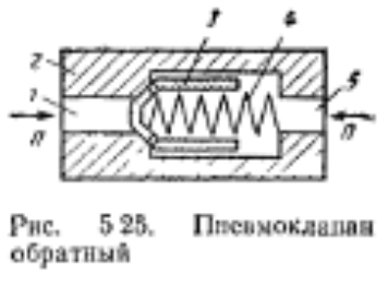
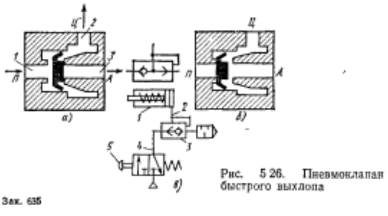
Quick exhaust valve(Fig. 5.20) serves to increase the speed of pneumatic actuators by reducing the resistance of the exhaust line. The use of such a valve (Fig. 5 26, c) provides an increase in the speed of retraction of the pneumatic cylinder rod / field by the action of the spring. When the pressure divider 5 is turned on, compressed air passes through the quick exhaust valve 7, which passes it into the piston cavity of the cylinder along the pipeline 2 % allowing the piston to move to the left.
When the pneumatic distributor 5 is turned off, the pressure in the pipeline 4 falls, the quick exhaust valve switches, ensuring the release of air from the cavity of the air cylinder into the atmosphere, bypassing the pipeline 4 to iisvmorraspredsligel 5.
On fig. 5.26a shows an arxewa quick exhaust valve. Hole 2 valve is attached to the cavity of the cylinder. The rounded air from the distributor is supplied to the opening /. Hole 3 is connected to the atmosphere. On fig. 5.26, o shows the position of the quick exhaust valve when the pneumatic cylinder cavity is filled with compressed air. On fig. 5.26.6 shows the position of the valve during the rapid emptying of the same cavity of the calmandra.
Sequence pneumoclalans designed to control the operating cycle by pressure (pressure difference) in pneumatic control systems by supplying a pneumatic signal when the controlled pressure (pressure difference) rises to a predetermined value. Such valves are also used to switch pneumatically controlled units in systems where limit switches cannot be used (for example, with a variable piston stroke).
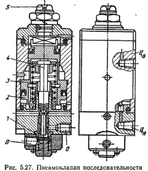
On fig. Figure 5.27 shows the construction of an active sequence valve. To avoid a false signal before and during the movement of the piston of the cylinder, a differential piston 2 is provided, the cavities of which communicate with the pressure (hole Ts p) and exhaust (hole C th ) cylinder cavities. Since before the start of movement and during the movement of the piston of the cylinder, the pressure difference in its cavities is less than after the end of the stroke, the differential piston 2 on- Rice. 5.27. The sequence pneumovalve is held securely in
upper position by spring 3, adjustable by screw 5, and pressure in the exhaust cavity acting on a large area of the piston 2.
After the passage of the piston of the cylinder to the extreme position and its stop, the pressure in the pressure chamber becomes equal to the pressure in the line, and in the exhaust cavity - atmospheric. As a result, the piston 2, overcoming the action of the spring 3> moves down and through the pusher 4 will mix valve Y, thereby connecting its output 0 to the power channel P. The output produces a pneumatic signal that can be used to reverse this pneumatic cylinder or control the piggy schema elements.
4 Pneumatic devices
Pneumatic devices are designed to control pressure and air flow Depending on the purpose, they are divided into the following categories
distributors information (input) devices, logic-computing devices and power amplifiers.
check valves.
flow regulators,
pressure valves
shut-off valves
Distributors vary
by the number of connected lines 2-linear. linear. 4-line, etc.
according to the number of switching positions 2 position 3 position etc.
according to the method of propulsion with muscle control with mechanical control with pneumatic control with electrical control
according to the method of resetting with spring return, with return using pressure
Figure 23 - Roller Lever Valve, 3/2 Roller Lever Breakable Valve
As a logic-computing device, the distributor is used, for example, to turn off or turn off the output signal, which is carried out under the action of the input signal
rice 2 5 Pneumatic 5G-distributor with double-sided pneumatic and auxiliary manual management
check valve
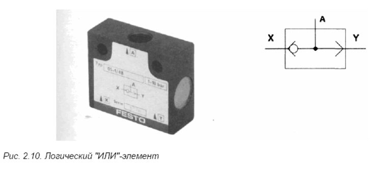
The non-return valve allows air to flow in only one direction. This principle is used, for example, in quick exhaust valves or OR logic elements. The non-return valve as a basic element is also used in other types of valves, which are shown in Fig. 2-6
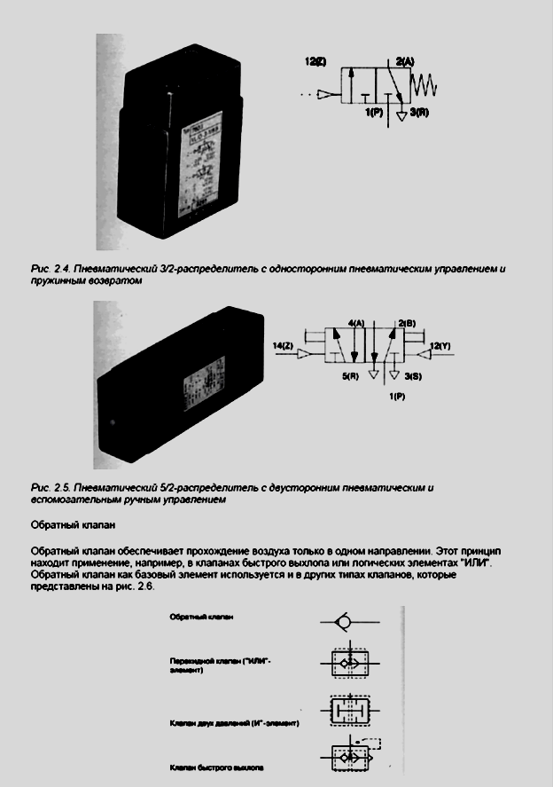
Fig 2 6 Check valve and other "valves" built but bang
Flow regulators
The flow regulator or throttle closes or throttles the lotto* and thus controls the compressed air flow Ideally, the throttle can be adjusted steplessly from full open to complete closure The throttle should be installed as close as possible to the actuator and adjusted as necessary during operation. If a non-return valve is connected in parallel with the throttle, then the air flow will be limited in one of the directions, and the flow will be maximum in the opposite direction.

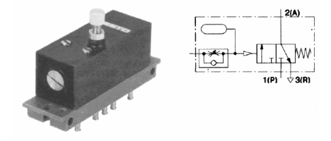
Fig 2 9 Time delay valve
Depending on the setting of the throttle screw, more or less air flow enters the tank. as long as the control signal is active Other modules with multiple valves include, for example
control devices with two inputs,
clock transmitters.
clock chains.
memory devices
Integrated mechanization and automation of technological processes in the manufacture of parts is aimed at improving the quality, productivity, equipment load factor, improving working conditions, and economic indicators of production.
To reduce auxiliary time in the machining of parts on metal-cutting machines, automation is subjected to such operations as installing, fixing and removing the workpiece, changing and replacing tools, monitoring parts on the machine, transporting and feeding workpieces to the working area, cleaning the metal-cutting tool from chips and its removal from the machine, etc. For these purposes, widespread use in technical systems find hydraulic and pneumatic actuators.
The hydraulic drive has a low inertia of moving parts, which ensures its high speed and allows you to quickly reverse and brake the actuator. The hydraulic drive has 3-10 times less weight and overall dimensions than the electric drive. It provides stepless speed control, is durable, the design of devices that prevent its breakage during overload is simple and reliable. The hydraulic drive makes it easy to automate motion cycles. The efficiency of hydraulic motors is in the range of 85-95%, which is higher than that of electric machines.
In CNC machines, hydraulic drives are most often used in feed movements and as servo drives. In chains of the main movement, they are used mainly in machines with reciprocating motion. In CNC machines, two power schemes for hydraulic motors are usually used: volumetric (from a hydraulic pump with adjustable output) and throttle (via a spool). The range of regulation of feed rates in CNC machines should cover both working feeds and fast movements. It reaches 10000 mm/min and above. It is necessary to ensure high accuracy and smoothness of movements at low working feeds (1-4 mm/min). Depending on the control system, feed drives are discrete (stepping) and servo. Stepper feed drive is used in open (without feedback) control systems. In stepper drives, stepper motors (SM) are used, which are low-power (control) and power. In drives with low-power stepper motors, hydraulic amplifiers are usually used as torque amplifiers. At the same time, the torque of the hydraulic motor can exceed the torque of the stepper motor up to 300 times.
To remove chips from machine tools, combinations of various types of devices are usually used. So, for example, the chips from each machine are washed off by a strong coolant jet and enter the common chute, along which it moves to the collector. In the collector, the coolant is separated from the chips and pumped back to the machines. Pneumatic devices are also used for chip removal, which come with pressure, suction and suction-pressure systems.
6. Means of pneumatic automation. Jet systems of pneumatic automation.
Along with power pneumatic devices, pneumatic devices are increasingly used in industry. They are used primarily in machines, which include only power pneumatic devices, in order to avoid the use of different types of energy.
To power pneumatic control systems from the factory network, three levels of compressed air pressure are used:
high pressure (4-10 kgf / cm 2);
medium pressure (1-4 kgf / cm 2);
low pressure (up to 1 kgf / cm 2) -. In accordance with this, pneumatic automation devices are divided into three groups.
7 Logic-computing elements (Processors)
For logical processing of the output signal of information elements, various relay elements are used, for example
logical "AND" - element,
logical *OR* element
Further development of pneumatic processors that process information is on the way to creating modular systems, which combine distributors and logic elements in one 6-layer This reduces the size and cost of installation 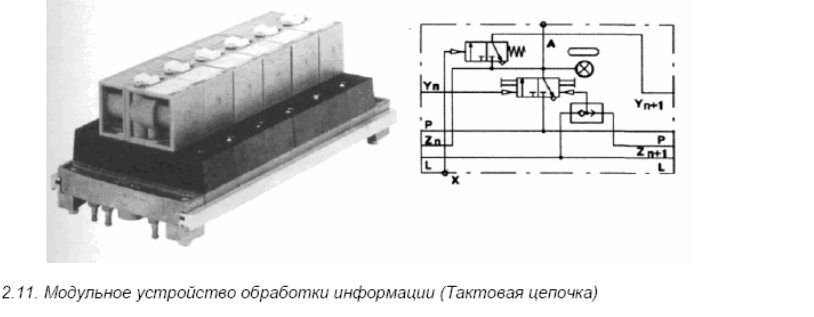
8.. General information about hydrodynamic transmissions
Hydraulic transmission? it is a device for transmitting mechanical energy through the flow of fluid. The structure of the hydraulic transmission includes a pump, a hydraulic motor and connecting pipelines with a working fluid. Hydraulic transmissions using dynamic hydraulic machines are called hydrodynamic.
In hydrodynamic transmissions, vane pumps and, as hydraulic motors, vane turbines are used. In real designs, a vane pump and a hydraulic turbine are extremely close and are located coaxially in a common housing. Since these two hydraulic machines have a common housing, in the future we will call the pump a pump wheel, and a turbine? turbine wheel. There are no pipelines in this design, so the liquid from the pump wheel immediately enters the blades of the turbine wheel, but from the turbine? again on the impeller blades.
Hydrodynamic transmissions used in mechanical engineering are divided into hydraulic couplings (fluid couplings) and hydraulic transformers (torque converters).
Fluid couplings, consisting of pump and turbine wheels, are used to transfer energy without changing the torque, i.e., the moments on the input and output shafts of the fluid coupling are almost the same.
Torque converters, in addition to pump and turbine wheels, have at least one additional wheel. It is motionless in most operating modes, i.e. is inactive (reactive), and therefore it is commonly called a reactor. The inclusion of a reactor in the torque converter allows it to change (transform) the transmitted torque. Thus, the moments on the input and output shafts of the torque converter are different in most operating modes.
A torque converter is called a complex torque converter, which, in a wide range of changes in its gear ratios, works like a torque converter, and at large gear ratios it switches to a fluid coupling mode and works like a fluid coupling. This allows you to significantly increase its efficiency.
Lecture 3
Drives for industrial robots.
1. Comparative characteristics of PR drives
2. Pneumatic drive:
- elements of the pneumatic drive;
– typical scheme and controls;
– pneumatic damping:
external devices,
working body;
– Positioning of the pneumatic actuator;
– Pneumatic servo drive.
3. Hydraulic drive:
- scope, advantages and disadvantages;
– Hydraulic motor diagram: elements and parameters
4. Electric drive.
5. Combined drive:
– electrohydraulic;
- hydropneumatic and pneumohydraulic.
Comparative characteristics of PR drives.
PR drives include a motor, a control system, transmission mechanisms, braking devices, feedback sensors and communications. Communications are needed to transfer power to the actuators and transmit control signals, as well as to perform feedback.
The choice of drive type depends on the functional purpose of the PR. The main factors determining the choice of drive type are: the purpose and operating conditions, load capacity and the required dynamic characteristics of the structure, as well as the type of control system.
To the drive of any kind present General requirements:
– minimum overall dimensions with high energy performance, providing a large value of the ratio of output power to mass;
– the ability to work in the automatic control and regulation mode, which provides optimal acceleration and deceleration laws with a minimum time of transient processes;
– performance, i.e. implementation of movements of actuators with high speeds and a small positioning error;
- low mass of drive elements with high efficiency of the entire structure;
– reliability and durability of structural elements;
- ease of installation, repair, maintenance, readjustment and quiet operation.
Depending on the type of energy used, drives are divided into hydraulic, pneumatic, electric and combined (for example, electro-hydraulic, hydropneumatic, etc.)
Pneumatic actuators are used in 20...30% (according to other estimates, 40-50%) of mass-produced PR. They are used for light and medium (in terms of load capacity up to 20 kg) PR with the number of degrees of freedom 2 ... 3. The positioning error in these drives does not exceed ± 0.1 mm. The speed of the driven link of the drive with linear movement is up to 1000 mm / s, with angular - up to 60 rpm. They have a simple design, low cost and are quite reliable in operation.
Due to their low adjustability, they are little used in positional and contour modes of operation, and they have cyclic control, as the simplest option positional (two points are set - the beginning and end of the movement).
hydraulic drives are used in 30% of mass-produced medium and heavy PR with the number of degrees of freedom 3 ... 4. The positioning error in these drives does not exceed ± 0.5 mm at a linear movement speed of up to 0.8…1200 mm/s. These drives have a complex design, high cost of manufacture and operation. The hydraulic drive has a good adjusting ability, and it is used in PR with positional and contour operation.
Electrical drives are used in 40…50% of mass-produced PR with an average load capacity and the number of degrees of freedom 3…6. The positioning accuracy of the electric drive reaches values up to ± 0.05 mm. They are used in both positional and contour modes of operation.
The advantages of electric drives are higher economy, efficiency, ease of assembly and good control properties.
As a rule, synchronous, stepper and motors are used in electric drives. direct current. Asynchronous motors are used less frequently, due to the complexity of speed control.
Combined drives allow you to maximize the advantages of individual types of drives. Most often, industrial robots use a combination of pneumatic and hydraulic drives (pneumohydraulic and hydropneumatic), as well as electric and hydraulic (electrohydraulic). In PR designs, pneumohydraulic drives are of limited use. in them as executive body a pneumatic cylinder is used, and the stabilization of its speed and hydraulic fixation is carried out by a hydraulic system.
In the hydropneumatic drive, hydraulic motors are used as actuators, and the pneumatic system is used to create the necessary pressure in the hydraulic system, which makes it possible to abandon hydraulic pump stations.
Pneumatic drive
Elements of the pneumatic drive
The pneumatic actuator is mainly used in PR with cyclic control. Functionally, such a pneumatic actuator can be divided into the following nodes:
- unit for the preparation of the working fluid (air);
– compressed air distribution unit;
- block of executive engines;
– compressed air transmission system between drive devices.
Air preparation unit is obligatory for PR with pneumatic drive. The air is dried and cleaned of dust.
Compressed air distribution unit contains devices with the help of which, according to a given program, it is possible to open or close the access of compressed air to the working cavities of the executive engines. Devices are used as distributors, where locking devices serve as spools and valves. Usually, pneumatic distributors are used with control from electromagnets and command devices. However, when certain conditions(explosive atmosphere, radiation) pneumatically controlled valves are used.
As a block of executive engines Cylinders with linear or rotary piston movement, single or double acting, are used. Each degree of mobility is provided with its own actuator (pneumatic cylinder), the design of which provides the specified displacements, speeds and forces.
The gripping device PR can also have a motor that provides capture of the object of manipulation, its retention during movement and release after installation at a given point.
The work cycle is performed by each engine in a certain sequence in accordance with the requirements of the technological process and is carried out according to the program executed by the robot control device, which is part of the SPU.
In compressed air transmission systems between drive devices, pneumatic lines of various sections are used, calculated based on the specified operating conditions.
Typical scheme and controls.
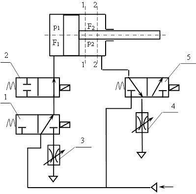
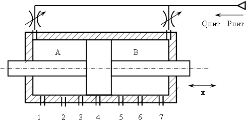
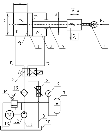
Consider a typical scheme of a pneumatic drive of one degree of freedom of the PR (Fig. 10). It consists of an inlet fitting 12, through which compressed air is supplied at a pressure of 0.5 ... 0.6 MPa from the factory pneumatic network to the PR. Valve 11 switches the drive into operation. The moisture separator 10 is used to prepare compressed air and remove water condensate from it, which causes corrosion and increases the friction of rubbing parts. Further, by means of an appropriate adjustment of the pressure reducing valve 9, the pressure of the compressed air supplied to the drive elements is preliminarily adjusted. This pressure is nominal and is set according to technical requirements for this PR. Oil atomizer 8 is also involved in air preparation and provides atomization of the oil necessary for lubricating the moving elements of the executive engine (cylinder 2) and distributor 6. The latter are used so-called. spools and valves. Usually the distributor is controlled by an electromagnet. Distributors are used to redistribute the flow of the working fluid, in this case compressed air, in accordance with the control program and the requirements of the process.
Rice. 10 - Typical diagram of a pneumatic actuator
According to the scheme shown in Figure 10, the piston 1 moves to the step S to the right together with the rod 3, hand 4 and the 5. Throttle 7 serves to adjust the speed of movement of the moving parts of the engine.
The main parameters characterizing the air motor include: the effective area of the piston in the working (piston) F 1 and exhaust F 2 (rod) cavities; piston stroke S; current coordinate x; speed v and acceleration a piston weight m p executive device (for example, PR hands); air pressure in the working p 1 and exhaust panels p 2; effective cross-sectional areas of pipelines at the inlet f 1 and exit f 2 ; piston diameters D and stem d; driving force R D and load force (required) R N.
The choice of parameters of the pneumatic cylinder is made as follows. Horizontal piston diameter:
for a vertical cylinder:
where p c - air pressure in the network (0.5 ... 0.6 MPa);
G is the weight of the actuator, N;
k 1 - coefficient taking into account the ratio R N / R D, selected depending on the speed v and pressure r s(on average k 1 = 0.4 ... 0.5);
k 2 - coefficient taking into account friction in the cylinder, selected depending on Р Н. At Р Н = 0.6 ... 60 kN, k 2 = 0.5 ... 0.05;
B - constant, B = 11.3;
G is the weight of the moving parts of the actuating device with the object of manipulation. "+" sign when lowering the piston, "-" sign - when lifting.
The length of the cylinder is chosen depending on the piston stroke, and for double-acting cylinders S=(8…10)D is recommended. With large piston strokes, the rod is counted on stability. Pneumatic cylinders with D=32…80 mm and stroke S up to 1000 mm are used in PR.
The load force РН is determined by the formula:
P N = P T + P I ± G (5)
where P T is the friction force;
R I - force of inertia, R I \u003d m p d 2 x / dt 2
The operating time of the pneumatic cylinder is the sum of the forward stroke time tPX, dwell time tAT and return time tOH. The forward run time is the sum of the time t 1 actuation of the distributor, air distribution to the cylinder and pressure rise time p 1, time t 1 piston movement along the way S and time t 3 during which the pressure p 1 rises to the operating pressure in the network r s.
Standing time tAT depends on the nature of the process. The return stroke time of the piston consists of similar periods, reverse t1 , t 2 and t 3 . The total operating time determines the speed of the PR for each degree of mobility.
Air consumption (uncompressed) for practical calculations, taking into account the turbulence of its flow for a polytropic process pV n = const(n is the polytropic index, for air n=1.4) can be determined by the formula:
 (6)
(6)
where μ is the flow coefficient, determined by the ratio of the actual outflow velocity to the theoretical one (for reference, depending on the standard form of local constrictions);
p 1 and p 2 - air pressure in the discharge and emptying cavities, respectively;
R – gas constant (for air R=287.14 J/kg K);
T 2 - temperature in the emptying cavity;
f 1 is the area of the inlet section.
The critical value of the ratio p 2 /p 1 , which is sought to be achieved to increase the speed of the output link, is equal to 0.529. This value is achieved by reducing the outlet air pressure, while the total air flow remains practically unchanged.
Damping of the pneumatic actuator
Due to the high speeds of the piston of the air motor, it is necessary to brake it at the end of the forward and reverse stroke. This improves positioning accuracy and reduces dynamic loads in the PR.
Two types of braking are used in PR pneumatic drives: with the help of damping devices or by throttling (Fig. 10).
When using damping devices (external devices) braking occurs in a small area at the end of the stroke when approaching the positioning point. When using chokes (braking by the working body) acceleration and deceleration is carried out for the greater part of the stroke, than the required law of change of kinematic parameters is achieved during the entire cycle of movement.
damper braking based on the damping of the energy of motion. The most widely used hydraulic dampers (Fig. 11) and smaller - mechanical .
The hydraulic damper works as follows. At the moment of braking, stop 1, which interacts with the air motor rod, sinks the movable part of the damper - piston 2 of hydraulic cylinder 3. Due to the displacement of oil through the conical slot 4 into cavity 5, piston 2 is braked. Smooth braking is ensured by selecting the damper parameters: the size of the conical slot 4, throttle parameters 8 and battery springs 7 6. Dimensions dd, bandl calculated from the known piston speed and the allowable braking stroke.
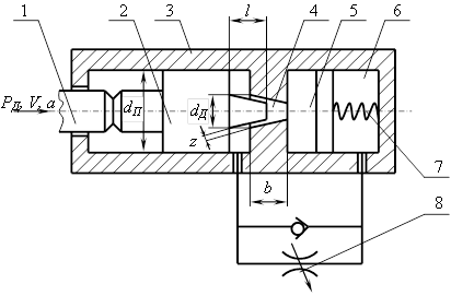
Rice. 11 - Scheme of the hydraulic damper.
The damping force R D can be determined by the formula:
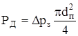 (7)
(7)
where Δр з is the pressure drop in the annular gap z;
d p is the diameter of the damper piston.
The pressure drop Δr s is determined by the formula:
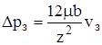 (8)
(8)
where μ is the dynamic viscosity of the liquid;
b is the length of the damping gap;
v W is the fluid velocity in the gap.
From the condition of fluid flow continuity we have:
where v is the speed of the piston of the executive engine;
f G is the area of the gap.
Then we finally get:
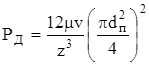 (10)
(10)
In mechanical dampers, the energy of the moving elements of the drive and the load is converted into the energy of a compressed spring. The design of the mechanical damper is made in the form of a cylindrical spring enclosed in a housing. Spring dampers are used for drives with a load capacity of up to 1 kg, since the spring parameters depend on the mass of the manipulated objects being moved, as well as on the speed.
The main parameter of the spring is the spring force P pr \u003d P D.
Tpiston braking using a working fluid is achieved by reducing the air flow from the emptying cavity by installing a special throttle (pos.7 fig.10) and allows you to change the area of the outlet section f 2 in law f 2 = f(x) . In this case, the pressure value changes and the necessary law of piston motion is formed, i.e. its speed is controlled. This method of braking is only possible due to the high compressibility of the air and is used for robots with a load capacity of up to 5 kg.
Another method of braking is a method in which a circuit for creating back pressure in the corresponding cavity of the engine is used. When the piston reaches a certain position, the main line pressure is supplied to the emptying cavity (Fig. 12).
Rice. 12 - Scheme of backpressure braking
The work is as follows. Compressed air from the supply line through pneumatic distributors 1 and 2 enters the left cavity of the cylinder. The right cavity is connected to the atmosphere through the pneumatic distributor 5 and throttle 4. The piston moves from the left position to the right, while the pressure drop on the piston Δр=р 1 -р 2 . When the piston reaches position 1-1 by means of the PR control system, the pneumatic distributor 5 switches to another position (to the left) and compressed air from the supply line enters the right cavity of the pneumatic cylinder. The pressure in both cavities begins to equalize to p 1 =p 2 . Due to the difference in the areas of the left and right parts of the piston F 1 and F 2, a force P \u003d p 1 (F 1 - F 2) acts on the piston, under the influence of which the piston will move at a lower speed.
To create a balance of forces on the piston, the pneumatic distributor 2 must switch simultaneously with the pneumatic distributor 5 and block the access of compressed air to the left cavity of the cylinder, which will be a closed volume V, for which we can take pV= const.
In case of equilibrium on the piston:
![]() (11)
(11)
where N are external forces (functional purpose).
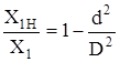
Expressing the area in terms of diameters, we obtain a condition that characterizes the equilibrium in the cavities of the cylinder through the pressure ratio:
(when N ext =0) (12)
where D and d are the piston and rod diameters, respectively.
Otherwise, the last formula can be rewritten as:
 (13)
(13)
where X 1Н and X 1 are the initial and final coordinates of the piston.
This formula obtained from the following expression, taking into account pV= const:
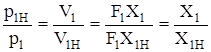 (14)
(14)
V 1Н and V 1 are the initial and final volumes of the left cavity.
In real designs d/D= 0.3...0.7. In this case, X 1 \u003d (1,1 ... 2) X 1H. Then it is obvious that after the signal to stop (after switching to the left of the pneumatic distributor 5 to the left) the displacement of the piston can be from 10 to 100% of the initial position X 1H.
The above dependences do not fully reflect the actual operating conditions, because do not take into account the forces of inertia, etc., and show a qualitative picture of the processes occurring when the piston is braked by back pressure (taking into account the forces of inertia is important and mandatory in all design, strength and other calculations!).
The considered method of braking by the working body is not the only one. There are many other schemes, but their common drawback is the reconfiguration of damping when conditions and the nature of the external load change.
This damping method is used for robots with a load capacity of up to 1 kg.
Positioning of the pneumatic actuator
The positioning of the output link (for example, US) in the PR with cyclic control is provided at two extreme points and is ±x max ; ±φ max - maximum and minimum piston stroke for linear and angular displacement.
In some cases, positioning of the output link at intermediate points is required. In this case, positioning is carried out using external mechanical stops with damping when approaching each stop (point). Calculations and practice show that there can be 6 ... 9 such positioning points in pneumatic drives and no more, due to the high compressibility of the working fluid (air) and the speed of movement.
The number of positioning points can be increased by using the so-called. positioners.
Most simple circuit positioning is presented on rice. 13.
Rice. 13 - Positioning scheme
The pneumatic motor is made in the form of a cylinder with a double-acting false rod. Nutrition is supplied to both cavities simultaneously. When the pressures in the cavities are equal, the piston is at rest. Lines 1 - 7 serve to release air into the atmosphere. When one of the outlets is opened at the command of the control system, the pressure in the corresponding cavity decreases. Under the action of the difference in forces, the piston will move until the outlet is blocked and the pressures in the cavities A and B are equalized. Closing and opening of the outlet can be carried out mechanically or by a pneumatic distributor. Mechanically, the outlet is closed by the piston itself.
This way of positioning the output link is used most often.
Another positioning method is the use of a mechanical brake, which serves to stop the output link. Braking is carried out in two stages, at the first - the speed of the output link is reduced by 5–10% of the maximum. Here, with the help of position sensors, braking points are determined, at which the further movement of the output link begins to slow down. At the second stage, the output link stops at a given point with the help of a brake.
Position control in PR pneumatic actuators is used for a wide range of load capacity from 0.1 to 20 kg. and speeds from 500 to 1000 mm/s.
Pneumatic servo drive
The use of a servo pneumatic drive would make it possible to solve the problem of using the contour control of the PR. As a result of this, the problem of precise as well as intermediate positioning of the PR output link would also be solved. However, the use of a servo drive in PR pneumatic devices is rarely used in practice, which is due to a number of circumstances, primarily with the properties of the working fluid (air).
circuit diagram servo pneumatic drive is presented on rice. 14-a.
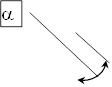
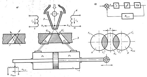
Fig.14 - Schematic diagram of the servo pneumatic actuator:
1 - cylinder; 2 – jet mechanism; 3 – receiver nozzles; 4 - control winding.
The compressed air distributor is the jet mechanism 2, when deviated to the right and to the left, there is a proportional change in the air flow into the left or right cavity of the cylinder 1 through the nozzles of the receiver 3. The armature of the electromagnetic transducer (EPM) is located on the jet axis (not shown in the figure). When diluting the control currents i y in the control windings, an equilibrium of forces acting on the armature occurs, which, together with the jet, is in the middle position. If there is a difference in control currents i y, the balance of forces is disturbed, the armature and the jet turn through an angle a, which is proportional to the difference in currents. The position sensor of the cylinder rod is a feedback potentiometer.
On the image rice. 14-b a block diagram of the drive that performs closed-loop control is presented. The comparison element U compares the control signal with the feedback signal and generates an error signal ε, which is fed to the controller, consisting of an amplifier > and a nonlinear element with a saturation zone f and integrator 1/r.
f– limits the signal in magnitude, 1/r– increases the accuracy of operation.
Follower pneumatic actuators are throttle control systems, because. changing the flow rate to the drive by changing the performance of the compressor that pumps air is unpromising due to the compressibility of the air.
The operating principle of the jet distributor is based on double energy conversion. First, in the jet tube, the potential energy of the compressed air is converted into the kinetic energy of the air jet flow, then, in the nozzles of the receiver, the kinetic energy of the jet flow is converted into the potential energy of the compressed air entering the working cavities of the cylinder. The pressure loss in this case is up to 10%.
Hydraulic drive
Scope, advantages and disadvantages
It was noted above that the scope of hydraulic motors for driving the PR is quite high and consists of 30% of mass-produced medium and heavy PR. The positioning error in these drives is quite small and does not exceed ± 0.5 mm at a linear movement speed of up to 0.8 ... 1200 mm / s. Hydraulic motors in PR are used, as a rule, for portable degrees of freedom.
Such a widespread use of hydraulic drive in PR designs is primarily due to their advantages, such as:
– high energy intensity;
- speed;
- low inertia;
- low compressibility working fluid and due to this, a sufficiently high rigidity of static load characteristics;
- a good opportunity to implement automatic control and regulation of the speed of actuators;
– reliability of work and operation.
Disadvantages: These actuators have a complex design, high cost of manufacture and operation, as well as the possibility of leakage and the need to cool the working fluid.
The following main types of hydraulic motors are used in PR hydraulic drives, which can sometimes be combined with various designs of mechanical transmissions:
- linear hydraulic cylinders with translational movement of the rod;
– rotary hydraulic motors with a limited angle of rotation;
- hydraulic motors.
All elements of hydraulic and pneumatic actuators are standardized and contained in the reference literature.
Unlike pneumatic motors, for hydraulic motors a power supply unit is provided, which is part of the PR. It contains a hydraulic pump, throttles, filters, pressure regulators and other devices. (Fig. 15).
Hydraulic motor diagram: elements and parameters
Rice. 15 - Hydraulic motor diagram
The PR hydraulic motor contains a piston 1, a double-acting cylinder 2, a rod 3 with a hand and a gripping device 4. Oil is supplied and drained by a hydraulic spool 5. The hydraulic motor also includes a pressure gauge 6, an accumulator 7, a throttle 8 (the speed of movement of the output link - the PR hand is regulated ), drain pipeline 9 and tank 10, as well as intake pipeline 11, hydraulic pump 12, electric motor 13, safety valve 14 and filter 15.
The main parameters of the hydraulic motor include: effective piston area in the working F 1 and drain F 2 cavities; stroke S; current coordinate x; speed V and piston acceleration a; weight m p PR hands; oil pressure in the working p 1 and drain p 2 cavities; effective cross-sectional areas of pipelines in the working f 1 and drain f 2 highways; piston diameters D and stem d; driving force R D and load force R N.
The load force is determined similarly to the air motor by the formula:
![]() (15)
(15)
where P t is the total friction force in the guides;
P and - the force of inertia, P and \u003d m p d 2 x / dt 2
G is the weight of all moving parts if the cylinder is vertical. "+" sign when lowering the piston, "-" sign - when lifting.
The driving force is the sum of the resistance force and the load force:
![]() (16)
(16)
where P c is the oil resistance force in the drain line, is determined by the product of the oil pressure and the area of the piston in the drain cavity of the hydraulic cylinder: .
The choice of the main parameters of the hydraulic motor, according to which the final selection of the brand and model of the PR can be made, is carried out as follows.
When the piston moves to the right.
In this case, the dimensions of the PR cylinder are related by an empirical relationship:
Dimensions D and d are substituted in mm., and F 1 and F 2 are obtained in cm 2.
The moving force is determined by the formula:
where k t is the coefficient taking into account friction losses, k t = 09…0.98.
R d is substituted in newtons, p - in megapascals.
Oil consumption and piston speed are related by dependencies:
![]() (19)
(19)
![]()
where Q is the flow rate, l/min;
V – speed, m/min.
When the piston moves to the left:
![]() ; (21)
; (21)
![]() . (22)
. (22)
For a given ratio of speeds V 1 and V 2 (when V 1< V 2 и количество поступающего в цилиндр масла const) the rod diameter is found from the expression:
![]() (23)
(23)
where D and d are in mm, and V 1 and V 2 are in m / min.
Piston diameter D and its length L choose from the conditions of the layout conditions of the PR node. Usually L/D = 18…20 is recommended, and for large displacements L/D>>18…20.
The parameters of the rotary vane motor are selected based on the following relationships.
Driving torque (in Nm) on the output shaft:
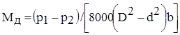 (24)
(24)
where p 1 and p 2 - pressure in the pressure and drain cavities, MPa;
b – blade width, mm;
D and d are the dimensions of the hydraulic motor.
Angular velocity(rad/s) output shaft rotation:
![]() (25)
(25)
where Q is the oil consumption, l/min.
The parameters of the hydraulic motor are selected based on the following relationships.
Driving torque on the output shaft:
![]() (26)
(26)
where q is the working volume of the hydraulic motor, cm 3;
p 1 and p 2 - pressure in the pressure and drain lines, MPa.
The speed of the output shaft (min -1) is determined by the formula:
![]() (27)
(27)
where Q is the oil consumption, l/min.
Electric drive.
Features, advantages and disadvantages
AT recent times in the world and domestic practice of PR application, the electric drive is increasingly used. They are not used only in robots designed to work in explosive environments and to work with machines equipped with hydraulic systems, for reasons of unification.
Electric drives of the new PR series are drives with high-torque DC motors, brushless DC motors, power stepper motors, and less often asynchronous motors.
The features of PR electric drives are an extended range of small torques (up to 0.05 Nm in total), an increased maximum rotational speed (up to 15 × 10 3 rpm), reduced motor inertia, the possibility of embedding electromagnetic brakes and various sensors, as well as mechanical and wave transmissions.
The main advantages of using electric drives in PR are as follows:
– compact design of engines;
– high speed;
– uniformity of rotation;
- high torque top speed;
– high degree of reliability;
– a wide range of regulation in terms of speed and positioning, as well as a change in load moments;
– the possibility of long-term operation in a braked mode;
- high accuracy of operation, which is ensured by the use of digital measuring system and high-precision impulse sensors;
– interchangeability of engines;
– compact design of various converters;
– low noise and vibration levels and availability of electricity.
The disadvantages of using electric drives in PR are as follows:
– limited use in explosive environments;
- dependence of the speed of the output link on the external one, which leads to the need to create additional drive control loops;
- the presence of an additional kinematic circuit between the electric motor and the working body of the PR.
Functional diagram of the electric drive
The electric drive of a modern PR is a complex of drives, each of which controls a separate degree of mobility. Consider, using the example of an electric drive PR model HdS05 / 06 (GdA, Germany), the most common functional diagram (Fig. 16).
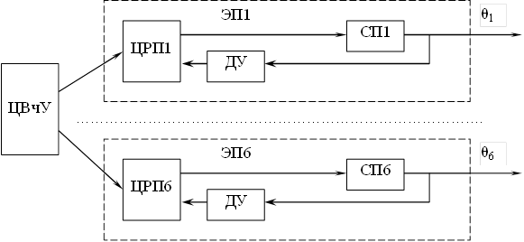
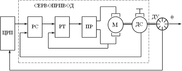
Rice. 16 - Functional diagram of the control of the electromechanical robot model HdS05/06.
This PR has six degrees of freedom, indicated on the diagram as θ 1 ... θ 6 . All six electric drives (EP1…EP6) are controlled from a common central computing device (CHU) of the program control system (SPU) PR. The central computer sends signals to the digital position controllers (TsRP1….TsRP6) of individual drives. Digital position controllers control servo drives (SP1…SP6) in accordance with the signals of the TsVChU and angle sensors (DU), for example, encoder angle sensors with photoelectric conversion.
One of the most complex and critical elements in an electric drive is a servo drive (SP).
The functional diagram of the PR servo drive is shown on rice. 17.
Rice. 17 - Functional diagram of the PR servo drive.
This scheme is an analog-digital automatic control system that combines the advantages of a combined analog system, operating on the principle of a three-loop slave control system, with the advantages of a digital system (high accuracy and ease of programming).
The first circuit is formed by a motor (M) with a converter (PR) and a current regulator (RT). The second circuit includes a speed sensor (DS) and a speed controller (RS). The third circuit additionally includes an angle sensor (DU) and a digital position controller (DRP).
As speed and current controllers in PR, analog, and more recently, digital operational amplifiers are most often used, with the help of which almost any required control law is easily implemented. The speed sensor can also be either analog or digital.
In some cases, the use of a speed sensor is not required, because. the speed change signal can be calculated in the digital position controller (DRP) by differentiating the signal from the angle sensor (DU)
Thus, the analysis of the functional diagrams shown in Fig.16 and Fig. 17 shows that regardless of the specific circuit, the PR electric drive consists of the following elements:
– actuating element (engine);
– converter;
– current, speed and angle regulators;
– and feedback sensors for current, speed and angle.
Modern trends in the development of robotics are such that they allow the production of servo drives that structurally combine a motor, a converter, sensors, and speed and current controllers.
[Previous lecture] [Contents] VIP user.This can be done completely free of charge. Read.
Pneumatic drive
A distinctive feature of modern production is the widespread use in equipment of high-tech components of the same type in terms of functionality and design for general industrial use. First of all, such components include various kinds of drives and systems.
A system is a set of interconnected objects united by a single goal and a common algorithm of functioning. If the objects are technical devices, the interaction of which is carried out by means of liquid or air, then such systems are called, respectively, hydraulic and pneumatic, or in short, hydraulic and pneumatic systems. The liquid and compressed air used in them is called the working medium. (energy carrier).
Depending on the functional purpose, hydraulic and pneumatic systems are divided into control systems - systems that are used to control various machines, and systems that provide the working process in these objects (lubrication systems, fuel systems, cooling systems, heat and gas supply, etc. . P.).
Control systems, which include a set of devices designed to obtain forces and movements in machines and mechanisms, are called drives. Depending on the energy source used, electric, hydraulic and pneumatic drives are distinguished.
The scope of this or that drive is determined by analyzing the advantages and disadvantages inherent in each of them (Table 1).
Tab. 1. Comparison of drives by type of energy used
| Criterion | Electric drives | Hydraulic drives | Pneumatic actuators |
| Energy costs | Low 1 | High 3…5 | High 7…10 |
| Energy transfer | Unlimited distance speed up to 300 km/s | For distances up to 100 m, speed - up to 6 m / s, signal transmission - up to 100 m / s | For distances up to 1000 m, speed - up to 40 m / s, signal transmission - up to 40 m / s |
| Energy storage | Difficulty | Limited | Easy to do |
| Linear movement | Difficult, expensive, little effort | Simple, great effort, good speed control | Simple, little effort, speed depends on the load |
| rotational movement | Simple, high power | Simple, high torque, low frequency | Simple, low torque, high frequency |
| Operating speed of the actuator | Depends on specific conditions | Up to 0.5 m/s | 1.5 m/s and above |
| Efforts | Great effort, no overloads allowed | Forces up to 3000 kN, overload protected | Forces up to 30 kN, overload protected |
| Positioning accuracy | +1 µm and above | Up to +1 µm | Up to 0.1 mm |
| Rigidity | High (mechanical intermediate elements are used) | High (hydraulic oils are practically incompressible) | Low (we compress the air) |
| Leaks | Not | Create pollution | No harm but waste of energy |
| Environmental influence | Insensitive to temperature changes | Sensitive to temperature changes, fire hazard | Virtually insensitive to temperature fluctuations, explosion-proof |
Equipment with pneumatic actuators, the working medium in which is compressed air, is characterized by simplicity of design, ease of maintenance and operation, high speed, reliability and durability of operation, functional flexibility, low cost, as well as the ability to work in aggressive environments, explosive -, fire and moisture hazardous conditions. Compressed air is easily accumulated and transported, and its leakage through seals, although undesirable, does not pose a danger to the environment and products, which is especially important for the food, perfumery, medical and electronic industries.
Pneumatic drives differ from electric drives in the possibility of reproducing linear and rotary movements without the help of converting mechanisms, in greater power density, and also in maintaining operability during overloads. At the same time, the response speed and maximum output power of pneumatic actuators powered by industrial pneumatic lines are less.
Compared to hydraulic drives, the advantages of pneumatic drives are the possibility of using a centralized source of compressed air, the absence of return lines and communications, lower tightness requirements, no environmental pollution, and high speeds of the output link. Pneumatic actuators are characterized by ease of control, freedom of choice of installation location, and low sensitivity to changes in ambient temperature.
At the same time, pneumatic actuators have some disadvantages that limit their scope. For example, due to the fact that the air pressure in centralized pneumatic lines, which is 0.4-1.0 MPa (4-10 bar), is significantly lower than the pressure level in hydraulic systems - up to 60 MPa (600 bar), pneumatic actuators have significantly lower energy consumption and worse weight and size indicators. Due to the compressibility of air, it becomes technically difficult to ensure the smooth movement of the output links of the actuators during load fluctuations, as well as their precise stop in any intermediate position (positioning) and implementation of the given law of motion.
In order to understand the purpose of certain elements of pneumatic systems, to understand the principles of their operation and combining them into general structures, we introduce some general concepts.
It is known that all technical processes are divided into:
technological — production and processing of materials;
energy - generation, transformation and transmission various kinds energy;
information - formation, reception, processing, storage and transmission of information flows.
Based on this, we can say that a pneumatic drive, like any other, consists of two interconnected main parts:
power, in which energy processes are carried out;
managing, implementing information processes
Drive elements, depending on their functional purpose, belong to its various subsystems. For example, devices used for the production and preparation of compressed air (such as compressors, filters, dryers, receivers, etc.) constitute the energy-supplying subsystem of the drive.
The energy management of the received compressed air, which consists in regulating its parameters such as pressure and flow, as well as in the distribution and direction of compressed air flows, is carried out by means of pressure valves, throttles, distributors and other elements of the guiding and regulating drive subsystem.
Useful work - the performance of various working movements or the creation of forces in machines, machine tools and technological installations - is performed by actuators (pneumatic cylinders, pneumomotors, grips, etc.), which make up the executive subsystem of the drive.
In the simplest drives, control functions remain with the person
Schematic pneumatic diagrams are usually built vertically (as well as block diagrams). The direction of movement of the energy flow (compressed air flow) on the diagrams of the power part of the drive is taken from the bottom up.
The implementation of management and control functions is always associated with the need to perform a number of operations of a logical and computational nature. Since the physiological capabilities of a person as control system are limited, the effective use of existing and the development of new high-performance plants are possible only with the transfer of control functions to machines. Thus, the task of automatic control is the implementation of the control process without the direct participation of a person.
Apply open and closed automatic control systems (ACS). In open systems, there is no control over the state of the controlled object, the control action is formed based on the purpose of control and the properties of the controlled object. In closed automatic control systems, the control action is made on the basis of the result of comparing the state - current or at control points - of the control object with a given (required).
The devices included in the control part of the closed control system are divided into two subsystems according to their functional purpose:
informational (sensory));
logic-computing (processor).
The information subsystem includes various kinds of input devices for external control signals, as well as sensors and indicators.
The purpose of the logic-computing subsystem is the processing of the input control signals in accordance with a given program and their output to the energy control devices in the power part of the drive.
Depending on the operating conditions, safety requirements or the degree of complexity of the power part of the drive, the control part can be implemented using pneumatic, electrical or electronic automation tools.
In most cases, the actuators of machine drives have a rigid or kinematic connection with the control object, which makes it possible to judge the corresponding state of the object by the state of their output links.
In automatic control systems, signals are transmitted via closed circuit. At the same time, the basic principle of constructing an ACS is implemented, which consists in applying feedback that ensures the transfer of information about a change in the state of the control object (or, about the state of the actuator) to the control system.
Automatic control systems operating according to such a scheme are classified: the type of control, the nature of the formation and type of transmitted signals, etc. Of the entire variety of pneumatic automatic control systems, discrete control systems are the most widespread, i.e. systems with a forced step-by-step process. In such systems, the program moves from the current step to the next one only on signals from the controlled system.
If the control part of the pneumatic actuator is not implemented on a pneumatic element base, then one speaks of a hybrid automatic control system. So, if the control system is made on the basis of electrical relay-contact devices or the control functions are carried out by an industrial controller, then we will talk about an electro-pneumatic control system.
Because electronic systems controls compare favorably with pneumatic ones in terms of speed, dimensions and ease of reprogramming, and in the general case it is more convenient to collect information by means of electronic sensors, then electro-pneumatic automatic control systems are increasingly being used to automate various technological processes.
2. Physical basis for the functioning of pneumatic systems
In all elements, devices and systems of pneumatic automation, the working medium is most often air pre-compressed in the compressor (in some special cases, other gases are used), which surrounds us in everyday life. Air is a gas mixture mainly consisting of two gases: nitrogen N2 (78.08%) and oxygen O2 (20.95%). In small quantities, it contains inert gases - argon Ar, neon Ne, helium He, krypton Kr and xenon Xe - and hydrogen H2 (0.94%), as well as carbon dioxide (carbon dioxide) CO2 (0.03%). In addition to these gases, the air contains some variable amount of water vapor (moisture).
The operation of pneumatic elements is based on the use of compressed air energy, as well as the physical effects that occur during its movement. The laws describing these processes are studied in detail in the course of fluid and gas mechanics.
2.1 Basic gas parameters
Pressure. If some external force acts on any closed volume of air through a movable element, such as a piston, then an internal pressure is created in the air, uniformly acting on all surfaces limiting this volume (Fig. 2.1). This provision follows from Pascal's law: the pressure exerted on the outer surface of a liquid ( gas) is transmitted to all points of this liquid ( gas) and is the same in all directions.
Rice. 2.1. An illustration of the operation of Pascal's law
The value of the internal pressure does not depend on the shape of the volume occupied by the air, and is determined as the result of dividing the module of the external force by the cross-sectional area of the piston:
P=F/S
In the international system of units SI, the unit of pressure will be N / m². This unit is called the pascal and is denoted Pa.
Pressure can be measured in various existing units (see Annex I.2). However, in practice, the pascal [Pa] unit should be used, as well as its derivatives, such as kilopascal [kPa], megapascal [MPa], etc.; bar [bar] is used as an exception:
1 bar = 105 Pa = 102 kPa = 0.1 MPa.
The pressure of atmospheric air on the objects in it and on the earth's surface is called atmospheric pressure and denoted Ratm. At each point in the atmosphere, atmospheric pressure is determined by the weight of the overlying column of air; its value decreases with height. Atmospheric pressure may vary depending on weather conditions and the geographical location of the area;
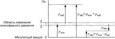
In pneumatic systems, as a rule, compressed air is used, the absolute value of the pressure Pa6s which is several times higher than atmospheric pressure. For the convenience of reading the pressure level in technology, the concept of overpressure is used.
overpressure Rizb is called the excess of the value of the absolute air pressure of the value of atmospheric pressure. The lack of absolute pressure relative to atmospheric pressure is called vacuum pressure or simply vacuum Рvac (Fig. 2.2).
Rice. 2.2. Pressure reference systems
Devices for measuring excess pressure are called manometers. Atmospheric pressure is taken as the zero point of the pressure gauge scale.
To measure the vacuum, vacuum gauges are used, the scale of which is graduated from 0 to -1 bar; The vacuum technique makes it possible to obtain a rarefaction p a6c ~ 10~10 Pa (10-5 bar). Instruments that measure both vacuum and overpressure are called manometers. There are also manometers for measuring absolute pressure, but they are used only in special cases. In theoretical calculations, the value of absolute pressure is always used.
Temperature. There are various scales for measuring temperature (see Appendix I.2), but at present only two of them are used - thermodynamic and International Practical, graduated respectively in Kelvin (K) and in degrees Celsius ( °C).
In the International Practical Scale, 0 and 100°C are, respectively, the freezing and boiling points of water (the so-called fixed points) at a pressure of 1.013. 105 Pa (1.013 bar).
All thermo- and gas-dynamic dependences include the thermodynamic temperature Г, which is counted from the absolute zero temperature, which is its theoretical value, at which gases do not have elasticity, and their volume becomes equal to zero.
The thermodynamic, or absolute, temperature G [K] and the temperature according to the International Practical Scale t [°C] are related by the relation T = t + 273.15.
Density. Another important parameter characterizing the state of a gas is the density p [kg / m³] - the ratio of the mass of a substance m [kg] to the volume F that this mass occupies:
P=m/V
Specific volume. Specific volume v [m³ / kg] is the reciprocal of density: v = 1/ρ.
2.2 Basic physical properties of gases
Compressibility. The property of a gas to change volume under pressure is called compressibility. Compressibility is characterized by the volumetric compression ratio β, which is the relative change in volume per unit pressure:
Sign “minus” in the formula is due to the fact that a positive increment (increase) in pressure corresponds to a negative increment (decrease) in volume V. The reciprocal of the coefficient β is called the bulk modulus of elasticity (compressibility modulus) K [Pa].
temperature expansion. Thermal expansion is characterized by the volumetric expansion coefficient βt [K1], which is the relative change in volume with a temperature change of 1 K:
Viscosity. The property of liquids and gases to resist shear ( slip) layers of liquid or gas is called viscosity. Viscosity is the opposite property of fluidity (the degree of mobility of particles of a liquid or gas): more viscous liquids are less fluid and vice versa. Viscosity can be characterized by dynamic viscosity ji and kinematic viscosity v.
The unit of measure for the coefficient of dynamic viscosity β, or coefficient of internal friction, is pascal second [Pa-s]. The unit of measure poise [P] of the CGS system is also used: 1 P = 0.1 Pa-s. The unit of the coefficient of kinematic viscosity v is m² / s; the CGS unit of stock [St] is also used: 1 St = 1 s m² / s = 1SI m² / s.
Viscosity depends on temperature (Fig. 2.3), and the nature of this dependence for liquids and gases is different: the viscosity of liquids decreases with increasing temperature, while the viscosity of gases, on the contrary, increases (for air, this dependence is insignificant).
Rice. 2.3. Dependence of kinematic viscosity v on temperature
![]()
2.3. Basic gas laws
The state of a gas is characterized by three main parameters - absolute pressure, absolute temperature and density (specific volume). The relationship of these gas parameters is called the equation of state. The state of the gas, called ideal, is described by the Clapeyron-Mendeleev equation
P =pRT,
Where Р is absolute pressure, N/m²;
p - density, kg / m³;
R is the specific gas constant, J/(kg - K); usually for air R = 287 J / (kg - K); T is the absolute temperature, K.
An ideal gas is such a gas in which there are no interaction forces between molecules, which are considered to be material points that do not have volume. Despite the fact that air is not an ideal gas, for most gas processes flowing at pressures not exceeding 20 MPa (200 bar), this equation remains fairly valid.
Entering into this equation a formula that determines the density through mass and volume, we obtain a relation that describes the state of m kilograms of an ideal gas with a volume V:
mR=pV/T
It is easy to see that for any constant gas mass, the left side of the equation is a constant value (constant):
pV/T=const
This equation generalizes the basic gas laws: Boyle - Mariotte, Charles and Gay-Lussac.
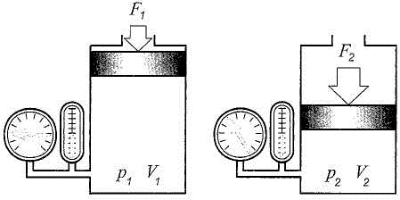
Boyle's Law - Mariotte. If the absolute temperature of a gas remains constant, then the product of the absolute pressure of a gas and its volume is also a constant value for a given mass of gas; in other words, the pressure of a gas is inversely proportional to its volume (Fig. 2.4).
Rice. 2.4. Illustration of Boyle's Law - Mariotte
Gas processes occurring at a constant temperature are called isothermal. If there is no heat exchange during gas compression environment, then such a process is called adiabatic (adiabatic). It satisfies the Poisson equation
p V = const,
where k is Poisson's ratio, or coefficient (exponent) of the adiabat (for air, k is 1.4).
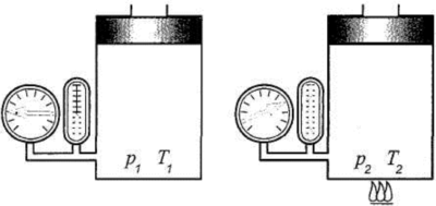
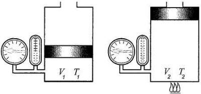
Charles' law. If the closed volume of a given mass of gas remains constant, then the ratio of the absolute pressure of the gas to its absolute temperature is also a constant value; in other words, the pressure of a gas is directly proportional to its temperature.
For example, when a gas is heated in a closed volume, its pressure increases, and when cooled, on the contrary, it decreases (Fig. 2.5).
Rice. 2.5. Charles' law illustration
Gas processes occurring at a constant volume are called isochoric (isochoric).
Gay-Lussac's law. If the absolute pressure of a gas remains constant, then the ratio of the volume of a given mass of gas to its absolute temperature is also a constant; in other words, volume is directly proportional to temperature.
For example, when a gas under constant pressure is heated, its volume increases, and when cooled, it decreases (Fig. 2.6).
p = const V1/T1=V2/T2
Rice. 2.6. Illustration of Gay-Lussac's law
Gas processes occurring at constant pressure are called isobaric (isobaric)*.
Since the parameters of the gas are interrelated and can vary over a wide range of values, the quantities of gas under different conditions, for the purpose of comparing them, lead to the so-called normal conditions.
The following parameters of normal conditions are generally accepted:
physical reference conditions: pressure 1.013.105 Pa (1.013 bar), temperature 273.15 K (0°C);
technical reference conditions: pressure 1.013.105 Pa (1.013 bar), temperature 293.15 K (20°C).
2.4. Gas flow
Above, we considered such gas parameters as pressure, temperature, density, specific volume. The flow of gas is characterized by one more parameter - the flow rate.
2.4.1. Consumption
Consumption - a value determined by the ratio of the mass (mass flow) or volume (volume flow) of a substance uniformly moved through a section perpendicular to the direction of the flow velocity, to the time interval during which this movement occurs.
In the technical literature, volumetric flow is denoted by the Latin letter Q (or Qv). The volumetric flow rate is determined by the ratio
Q=V/t
where Q - volume flow, m 3 / s; V is the volume, m 3; t is time, s.
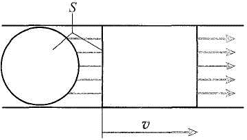
If we are talking about the flow of gas, for example, through a pipeline, then the volume flow can also be represented as the product of the cross-sectional area of \u200b\u200bthe pipe and the average cross-sectional velocity of the gas in it (Fig. 2.7):
Q=vS,
where v is the average flow velocity over the section, m/s;
S is the cross-sectional area of the pipeline, m 2.
Rice. 2.7. Volume flow
The mass flow Qm [kg/s], in contrast to the volume flow, depends on the density p [kg/m³] of the gas and is determined from the ratio
Qm=pvS
It is easy to see that there is the following relationship between volumetric and mass flow rates:
Q=Qm/p
In general, a gas is considered to be a compressible viscous liquid. Simultaneous consideration of the fact that the gas is a compressible medium and that the action of friction forces is manifested during its movement significantly complicates the calculations. Therefore, in practice, in many cases, they resort to the idealization of gas motion processes, which simplifies calculations without leading to large errors.
To understand the essence of the processes occurring during the flow of gas, we will consider it as an incompressible inviscid (ideal) liquid.
Based on the law of conservation of matter, as well as the assumption of continuity (continuity) of the flow for a steady flow * of an incompressible fluid, it can be argued that the volume flow through any section is the same (Fig. 2.8).Rice. 2.8. Fluid flow rate during flow through a pipe of variable cross section
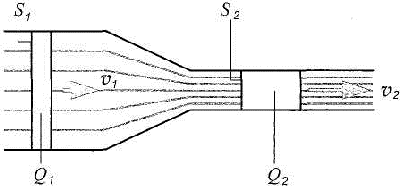
This phenomenon is described by the continuity equation
Q 1 \u003d S 1 v 1 \u003d S 2 v 2 \u003d Q 2 \u003d const.
From this equation it follows that in a narrow section of the pipe the flow is accelerated:
v 2 \u003d v 1 S 1 / S 2
2.4.2. Bernoulli equation
The results of pressure measurements at various points in a flow moving through a pipe with a variable cross-sectional area (Fig. 2.9) may seem, at first glance, paradoxical: in a narrow section, the pressure is less than in a wide one. What are the reasons for this phenomenon?
Rice. 2.9. Fluid flow through a pipe of variable cross section
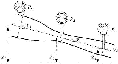
The mechanical energy of a moving fluid can take three forms: position energy, pressure energy, and kinetic energy. During the movement of an ideal fluid, one form of energy can be converted into another, but the total specific energy of the fluid remains unchanged. Mathematically, this situation is described by the Bernoulli equation
gz 1 +p 1 /p+v 1 2 /2=gz 2 +p 2 /p+v 2 2 /2= gz 3 +p 3 /p+v 3 2 /2
where gz is the specific energy of the position (g - 9.8 m / s 2 - acceleration of free fall); p is the specific pressure energy; v 2 / 2 - specific kinetic energy.
Thus, the decrease in the pressure level of the liquid in the narrow section of the pipe is due to the fact that the acceleration of the flow is accompanied by an increase in its kinetic energy and, consequently, a decrease in the pressure energy.
In some cases, it is convenient to use the form of writing the Bernoulli equation, in which the terms of the equation have the dimension of pressure:
gz 1 +p 1 +v 1 2 /2=gz 2 +p 2 +v 2 2 /2
where pgz is the weight pressure;
p is hydromechanical pressure (or simply pressure); pv 2 /2 - dynamic pressure.
In practical calculations, it is unacceptable to neglect energy losses along the length of the pipeline, as well as on local resistances. All real liquids and gases have viscosity, and therefore the energy of a liquid or gas flow will decrease from section to section in the direction of its movement. Energy losses are determined by many factors: the cross-sectional area and length of the pipeline, the roughness of its inner surface, the presence of local resistances, the speed and flow regime, the viscosity (internal friction) of the liquid or gas.
The Bernoulli equation for the flow of a real (viscous) fluid in energy form will have the following form:
gz 1 +p 1 /p+α 1 v 1 2 /2= gz 2 +p 2 /p+α 2 v 2 2 /2+gΣhn
where α is the Coriolis coefficient, taking into account the uneven distribution of velocities over the cross section
flow; g Σhn are total energy losses (hydraulic losses).
The Bernoulli equation is applicable to the flow of compressed air, provided that its speed v<υ, где υ — скорость звука.
2.4.3. Flow regimes
There are two modes of flow of liquids and gases through a pipe: laminar and turbulent (Fig. 2.10).
Rice. 2.10
Turbulent mode
The laminar regime is characterized by an ordered movement (layers) of a liquid or gas, and the speed of the outer layers is less than the inner ones. When the speed of movement exceeds a certain critical value, the layers begin to mix, vortices are formed; the flow becomes turbulent, energy losses increase.
When fluid flows through a pipeline, the transition from laminar to turbulent is observed at the moment when the flow velocity averaged over the pipe cross section becomes equal to the critical one V K .
As the experiment shows, the critical speed is directly proportional to the kinematic viscosity v of the liquid and inversely proportional to the inner diameter of the Cut:
Vcr=kv/d
where k is the coefficient of proportionality; v is the kinematic viscosity of the liquid, m²/s; d is the inner diameter of the pipe, m.
It was also experimentally confirmed that the change in the regime of the flow of any liquid or gas through a pipe of any diameter takes place only at a certain value of the dimensionless coefficient k. This coefficient is called the critical Reynolds number:
Recr= Vcrd/v
For round pipes ReK ~ 2300.
The Reynolds number is used to describe the flow regime:
Re=Vd/v=vpd/μ
The value of the Reynolds number makes it possible to judge the nature of the fluid flow through the pipe: at Re
Thus, knowing the flow velocity, the fluid viscosity and the inner diameter of the pipe, it is possible to calculate the Reynolds number by calculation and, comparing it with the ReKp value, determine the fluid flow regime.
2.4.4. Gas flow through a hole
When calculating pneumatic systems, it is necessary to know the dependences of the volumetric and mass flow rates of air through the hole on the ratio of pressures at the inlet to the hole and at the outlet of it. If we neglect the heat exchange of the gas with the environment and the internal friction of the gas, then its flow can be considered isentropic (adiabatic).
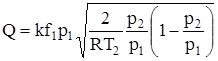
Mass flow in isentropic flow is calculated using the Saint-Venant-Wanzel formula:
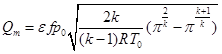
where e is the flow rate of the hole (it takes into account the compression of the jet during the outflow of gas;
usually determined experimentally); f is the hole area; π=p 1 /p 0 , p 0 - inlet pressure (usually take pQ=const);
p 1 - outlet pressure;
k - Poisson's ratio (adiabatics), for air k- 1.4; R is the specific gas constant, usually for air R = 287 J/(kg K); T 0 - air temperature in front of the hole.
If, on the basis of this formula, to construct a graph of the function Qm \u003d f (n), then it will look similar to the character of the dotted curve in Fig. 2.11.
Rice. 2.11. Mass flow rate Qm versus pressure ratio π=p 1 /p 0
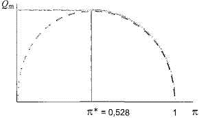
Function Qm =f (π) reaches its maximum at the critical value π = 0.528. However, it has been experimentally established that a decrease in the outlet pressure (leading to a decrease in the value of k) is accompanied by an increase in the air mass flow rate Qm only as long as the air flow rate does not exceed the speed of sound, the maximum possible outflow velocity in the absence of special devices. A further decrease in outlet pressure does not affect the mass flow (solid curve in Fig. 2.11).
For values 0<π<π* массовый расход подсчитывают по формуле
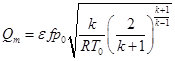
The process of gas outflow at π< π* называют докритическим (подкритическим ), а если отношение давле-ний π>π * then they say, respectively, about a supercritical (supercritical) or critical process.
To calculate the volume flow, the mass flow must be converted to density (see section 2.3.1 "Flow"). Since, when flowing through the hole, the values of air density at its inlet and outlet are different, i.e. p \u003d f (p), then the values \u200b\u200bof the volume flow will also differ: at the inlet Q V 0 \u003d Q (p 0), at the outlet Qv \u003d Qm (R).
It is necessary to pay attention to the following feature of the flow of gases (in particular, compressed air): the volumetric flow rate of gases (for example, when flowing through a diaphragm) depends (unlike the flow rate of liquids) not only on the pressure drop Δp = p 0 -p but also on the pressure level at the inlet p 0 (Fig. 2.12).
Rice. 2.12. Flow characteristics for a diaphragm with a cross-sectional area of 1 mm 2
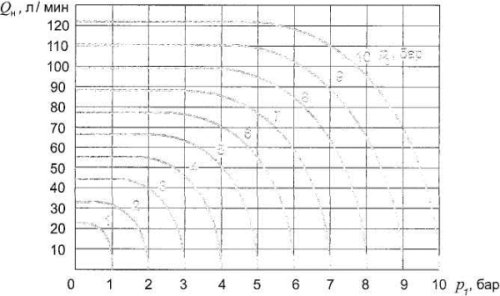
The above characteristics show that with a pressure drop Δp = 0.1 MPa (1 bar) and an initial compressed air pressure p = 1 MPa (10 bar), the flow rate Q H under technical normal conditions through the diaphragm is 70 l / min, and with this the same value Δp = 0.5 MPa (5 bar) - only 50 l / min.
Pneumatic valve actuator (pneumatic actuator) is one of the types of pneumatic actuators. The pneumatic actuator is used for automation and mechanization of pipeline fittings. This device has found the widest application in many industries, and plays a very important role in technological processes in many industries.
Most often, the pneumatic actuator is operated for the purpose of remote control of pipeline valves, their closing and opening, as well as in order to determine the position of the valve. In addition to pneumatic actuators, other types of actuators such as electromagnetic, electric and hydraulic are also used in valves.
Unlike electric actuators, pneumatic actuators are mostly used for shut-off (protective) valves, as they have their own specific features, however, in some cases, pneumatically actuated valves can play the role of control valves.
The use of pneumatic actuators is not too frequent, since a special compressed air compressor system must be installed in the enterprise to use these devices.
Piston drives
Piston drives are a cylinder in which a piston is moved under the influence of a spring or compressed air. Actuators of this type are used to control a wide variety of fittings - dampers, taps, gate valves, valves.
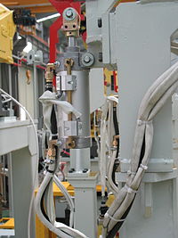
The most important are such Advantages of piston drives:
- Force limitation is carried out in the simplest way, namely, by limiting the pressure in the drive;
- A small number of parts that are used, and the simplicity of the design as a whole;
- The possibility of obtaining large forces and large strokes with a rectilinear stroke of the rod;
- Speed when using pressurized gases or compressed air as a control medium. This quality is decisive for most areas in which piston actuators of valves are used.
Piston drives can be subdivided:
- The layout method. They can be built into the design of the fittings, or be in the form of a separate unit;
- Without a connecting rod with a swinging (rotary) cylinder or with a connecting rod and a fixed cylinder;
- By the nature of the movement of the output link - rotary and linear;
- According to the operation cycle - for double-acting drives and single-acting drives;
- According to the properties of the control medium - hydraulic and pneumatic;
Double Acting Actuators
In double-acting piston drives, reverse and forward strokes are achieved by the action of the control medium. Drives of this type are easy to operate and control, have a simple device. However, there may be additional requirements for double-acting actuators when working in hazardous production facilities. For example, the following: in the event that there is no control medium, or an emergency shutdown occurs, the valve must not change the position that has been set up to this point. In such cases, double-acting actuators are equipped with special devices that provide fixation of the achieved position. However, the provision of these devices complicates the design of the drive.
Single acting actuators
Single-acting actuators differ from double-acting actuators in a more complex design due to the fact that they have a spring, which, during the forward stroke, is cocked in order to reverse.
The return spring must have the required travel and sufficient force. In view of this, in a large number of cases, this affects the fact that it has a significant size. At high forces, belleville springs are often used, which are in the form of a set of several springs, due to the fact that the stroke of an individual belleville spring is small.
To the main advantages of a piston drive single-acting include the possibility of making a move under the force of the spring even in the absence of a control medium, as well as the speed during the execution of this cycle.
From shortcomings it can be noted that it is necessary to have a drive of increased dimensions both in diameter, since in a straight stroke, in addition to overcoming frictional forces and useful work, there is a need to overcome the compressive force of the return spring, and along the length, which is necessary in order to accommodate the spring, which is usually located behind the piston.
Drives with rotational movement of the output shaft
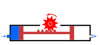
In rotary type actuators, the output stem rotates, which is typically a quarter turn to operate valves, or a 90 degree angle. There are also designs that create several turns of the output link, and are intended for valve control.
In order to convert the translational movement of the piston into rotational movement, which makes the output shaft of the drive, a rack and pinion gear, a crank mechanism, and in very rare cases, a screw motion converter are used.
Integrated piston drives
Built-in piston actuators are of the same design as the valve and have parts in common with this valve. This type of drives can be one-way and two-way movement.
The use of built-in piston drives is usually carried out in the main valves of impulse safety devices of power plants with high power, for example, nuclear power plants.
Integral drives create compact designs, but reduce maintainability and make them difficult to maintain. This is due to the fact that access to the drive is complicated, and in order to carry out repair work, it is necessary to disassemble the entire structure.
Integral single-acting piston actuators are also used in a variety of pressure regulator pilots.
Bellows actuators
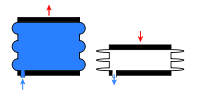
Due to the fact that bellows have the ability to change their length under the influence of medium pressure, they can be used as a drive designed to control valves.
The small size of bellows, as well as the small forces that can be generated with their use, determine the areas where bellows actuators are used - these are valves that have small dimensions, as well as a variety of pilot (control) devices in valves, as well as a variety of relays designed to control fittings, for example, in positioners.
When the pressurizing bellows needs to lengthen, its internal cavity is used to supply the control medium. If, on the contrary, the bellows should shorten when the pressure is increased, the medium must act outside the bellows.
For pipeline fittings, the most striking example of the use of a bellows pneumatic actuator is a thermostatic condensate trap, which is equipped with a bellows made of semi-tank. A special liquid is poured into the bellows, which quickly evaporates at temperatures exceeding 100 degrees Celsius. The vapor of this liquid creates pressure inside the bellows, it lengthens, and the spool that is located on it closes the hole in the trap seat.
Bellows actuators are always used as single acting actuators. The return force is generated by exploiting the elastic properties of the bellows. If this force is insufficient, an additional return spring is installed, which is located coaxially with the bellows outside or inside the latter.
The main disadvantages of bellows actuators include a limited cycle life, low generated force, low stroke, as well as the inexpediency and impossibility of repairing the bellows, as a result of which, if it fails, the entire bellows assembly of the valve actuator needs to be replaced.
Rotary vane drives
In a rotary actuator, the output shaft rotates due to the fact that one side of the blade, which is rigidly connected to the output shaft, is subjected to pressure exerted by the control medium.
One can distinguish single-blade drives, in which the angle of rotation of the output shaft can reach 180 degrees, and two-blade drives, in which this angle is slightly more than 90 degrees.
Assuming that both single vane and double vane actuators are used at the same control pressures and have the same vane size, the torque produced by a two vane actuator is approximately twice that of a single vane actuator.
An important factor is to ensure the tightness of the drive housing and the movable connection of the blade, since the slotted gap here has a rather large length. This system is also used in hydraulic drive systems as rotary hydraulic motors, which are also called vane motors.
Diaphragm actuators
The membrane actuator is a chamber that is divided into two cavities by a membrane. The movement of the driven link is transmitted under the action of a liquid or gas to an elastic (elastic) membrane made of metal, rubber or polymeric materials (fluoroplastic, polyethylene, etc.).
The force that is created due to the pressure of the working medium on the membrane is transmitted to the fungus formed by the support disk and the rod. The movement of the rod is translational, the value of the deflection of the membrane and the stroke of the rod is determined by the equilibrium condition of the movable drive system, the elements of which are the membrane and the fungus.
The force balance of the system is carried out subsequently by the action of the force that is created by the control pressure on the membrane, as well as the resistance forces that act on the rod (including also the force that is created by the elastic deformation of the membrane).
To provide the rod with the ability to move in both directions, the force closing of the system is carried out with the help of a load or with the help of a balancing spring. Springless drives are also used, in which the balancing of the moving system is carried out by means of the fact that air presses on the membrane block from the opposite side.
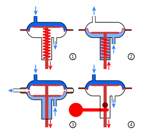
Schematic diagrams of the operation of membrane actuators are shown in the explanatory figure:
1 - spring direct action;
2 - spring reverse action;
3 - springless;
4 - lever-cargo.
AT lever-load diaphragm drives the force that is created on the membrane is balanced by the constant force of the weight of the load.
AT spring diaphragm actuators- using a variable force that is proportional to the stroke of the rod.
AT springless diaphragm actuators the acting force (pressure) on the membrane block can be regulated both from one side and from the other side.
In pipeline fittings, the diaphragm actuator is mainly operated with a rubber (in some cases with a fabric layer) membrane, molded, flat assembled or flat.
In all cases, the transfer of force to the rod from the membrane is carried out using a support disk, which forms a support platform for the membrane. By using a transmission lever, the diaphragm actuator can also be used in valves with a rotary shut-off device, i.e. dampers.
The membrane actuator has found the widest application in control valves. Through its use, the plunger is moved and installed in the position determined by the command signal. Much less often, in addition to spring actuators, springless actuators are used in pipeline valves.
In addition to being used in control valves, springless and spring-loaded diaphragm actuators can be used in both shut-off and globe valves. However, in this case, an additional requirement is imposed on these devices - at the end of the stroke, a force must be created that will ensure the sealing of the closed shut-off element in the valve.
Advantages of pneumatic actuators
Among the advantages that pneumatic actuators have, the following can be noted:
- Unlike hydraulic actuators, pneumatic actuators are less sensitive to changes in ambient temperature due to the fact that the efficiency is less dependent on leakage of the working gas (working medium). Due to this, a change in the viscosity of the working medium and a change in the gaps between the parts of pneumatic equipment do not have a particularly serious effect on the operating parameters of the pneumatic drive. Due to this, the pneumatic drive is convenient for operation in hot shops of metallurgical enterprises.
- Compared to a hydraulic drive, a pneumatic drive is capable of transferring kinetic energy over a distance of several kilometers, so it can be used as a main line in mines and mines.
- The neutrality of the working environment and fire safety, thanks to which the pneumatic drive can be operated in chemical industries and in mines.
- High response speed, as well as high rotational speeds of pneumatic motors, which can reach several tens of thousands per minute.
- Profitability and simplicity, which are due to the cheapness of the working gas.
- The possibility of simplifying the system by using a compressed gas cylinder as an energy source. Systems of this type are sometimes used instead of squibs, there are systems in which the pressure in the cylinder can reach 500 Megapascals.
- Compared to electric ones, lower weight of actuators.
- In comparison with the hydraulic drive - less weight of the working fluid. This factor is relevant for rocket science.
- Unlike a hydraulic drive, there is no need to return the working fluid (air) back to the compressor.
Disadvantages of pneumatic actuators
Of the disadvantages of pneumatic actuators, it is necessary to mention:
- In order to regulate the amount of rotation of the drive rod, it is necessary to use special expensive devices - positioners.
- The possibility of industrial injuries or explosive rupture of pipelines, as a result of which small working gas pressures are used in industrial pneumatic actuators, which usually do not exceed one Megapascal. However, systems are known in which the operating pressure is up to 7 megapascals, for example in nuclear power plants. Where there is no such problem (on airplanes and rockets), or systems are small, pressures can reach 20 MPa or more.
- Low smoothness and accuracy.
- Lower efficiency than a hydraulic drive.
- Higher, in comparison with electric, the cost of pneumatic energy (approximately 3-4 times). This is important when using a pneumatic drive, for example, in mines.
- Cooling and heating of the working gas during expansion in pneumatic motors and compression in compressors. This disadvantage is due to the laws of thermodynamics, and can lead to problems such as condensation of water vapor from the working gas, as a result of which it is necessary to dry it, as well as the possibility of freezing of pneumatic systems.
Hydraulic drives
All types of actuators listed above can be implemented with liquid. Most often, oil is used as a working medium.
In some cases, such devices will be more efficient than pneumatic actuators, for example, rotary vane actuators are significantly more efficient when used with oil as a working medium. This is due to the fact that significant air leakage through the slot gap is possible.
Advantages of hydraulic drives
The main advantages of hydraulic drives include:
- Simplified, in comparison with other types of drives, the layout of the main components of the hydraulic drive inside the units and machines.
- With simultaneous transmission to several drives, the possibility of uniform distribution of forces.
- Possibility of fast and frequent switching during rotational and reciprocating reverse and direct movements.
- Simplicity in the implementation of different types of movement - rotary, rotational, translational.
- The possibility of obtaining large powers and forces with a low weight of the transmission mechanism and small dimensions.
- Self-lubrication of rubbing surfaces in cases where synthetic and mineral oils are used as working fluids.
- High transmission power per unit mass of the drive. Thus, the mass of a hydraulic machine is about 10-15 times less than the mass of an electric machine of the same power.
- Reliability in operation.
- Ease of automation and management.
- The hydraulic drive creates smaller volumetric leaks through the piston-cylinder interfaces and through the stuffing box.
- The use of hydraulic actuators allows significantly higher pressures of the working medium. As a result, smaller designs can be used.
- Hydraulic actuators do not create shocks at the end of the piston stroke. This is due to lower piston speeds in hydraulic drives. However, low speeds of movement of working bodies in hydraulic drives in some cases can become their disadvantage.
- For the same reason, the movement of a piston or a hydraulic motor shaft in hydraulic drives is more uniform, while the operation of a pneumatic drive is often associated with a pulsating movement of the piston due to higher working gas velocities at pressures exceeding one megapascal.
Disadvantages of hydraulic drives
Of the disadvantages of hydraulic drives, it is worth mentioning:
- Due to oil leaks, production facilities are polluted, in addition, oil is a fire hazard;
- Typically, hydraulic actuators operate at lower piston speeds. This is due to the large hydraulic resistance in the supply pipelines of the drive control system.
- For the drive control system, it is necessary to purchase more expensive and larger equipment - a pumping station, while pneumatic drives require a compressor station.
- When compared with electric and pneumatic drives, it is impossible to effectively transfer hydraulic energy over long distances. This is due to the large pressure loss in hydraulic lines per unit length.
- The viscosity of the working fluid, and accordingly, the operating parameters of the hydraulic drive, depends on the ambient temperature.
- The hydraulic system must be protected from the penetration of air into it, which, if present, leads to heating of the working fluid, large hydraulic losses and unstable operation of the hydraulic drive.
- During operation, it is necessary to ensure the purity of the working fluid. This is due to the fact that if it contains a large amount of abrasive particles, hydraulic equipment parts wear out faster, gaps and leaks through them increase, and as a result, volumetric efficiency decreases.