
Lada gas stove device. Gas stove: device, replacement, connection, minor repairs
For the kitchen, they occupy a special place among the assortment of this equipment. They also differ in configuration and built-in functions. In addition, the popularity of this equipment is due to the ease of operation and installation. The service life of a gas stove is at least 10 years.
Gas oven for kitchen
Plate and its device
Modern gas ovens, unlike its predecessors, has a high level of security. This is ensured by a special control system. It blocks the gas supply in case the fire in the burner goes out or does not ignite. This prevents leakage, which can lead to gas poisoning, explosion, and other negative consequences.
The device of a gas stove is quite simple, however, additional functions are built into many models, such as:
- The system of temperature sensors, turns off the fire when the permissible heating level is exceeded;
- Timer;
- Smooth temperature control;
- A convector is an important device that provides uniform heating of the air.
In stores there are also combined ovens. Such models are popular because they combine the advantages of two devices operating from two types of power sources.
Gas burner device
The burner is the main element of the stove. It has an injector that supplies gas from the internal manifold. The upper part of the burner is a splitter that provides an even spread of fire for the most efficient heating.
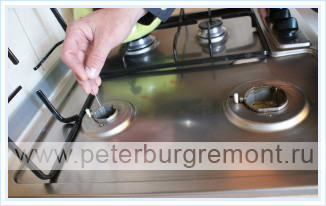
Gas burner - a device that ensures stable combustion of fuelIt is safe to remove the divider and its cover when cleaning the stove. However, it is worth making sure that the injector tube does not clog. To achieve the best effect, you should use special chemical protective equipment and do not use abrasive objects.
Directly under the divider is a nozzle that regulates the amount of incoming gas. Thanks to a special pressure adjustment system, stable fire is ensured in all burner operating modes. When choosing gas stoves special attention is paid to the parameters of the burners, as they are responsible for the formation of the mixture and its combustion. For the convenience of the user, modern models This technique has a built-in electric ignition. Despite the apparent simplicity, the gas stove burner device has its own characteristics. Therefore, to install the equipment, it is worth calling the master. The correct setting of the gas stove and the gas supply mode depends on this, which will ensure the efficient and safe use of the equipment.
Types of gas stoves
When choosing a suitable gas stove, the consumer focuses on two indicators: functionality and appearance. Therefore, manufacturers offer an extensive range of devices that differ in external and internal indicators.
There is a wide variety of boards on the market today.Functional content
The first thing you pay attention to when choosing a stove is the ignition button. Thanks to it, there is no need to constantly use matches. And the question: “How to set fire to a gas oven?” Does not arise. Electric ignition is installed in the stoves, which is started using a special button. This produces a spark that ignites the gas. In more expensive models, manufacturers install auto-ignition. This function ignites the burner automatically when the knob is turned. The system also automatically turns off the gas supply in case the fire goes out for some reason. Due to this, a high level of safety of the stove operation is ensured.
A dielectric insert for a gas stove is an integral part of modern devices in this group. It prevents the spread of leakage currents, which increases the safety of the equipment. As a result, the oven electronics and the electrical circuits of the appliance are protected.
Varieties of ovens
Another fundamental difference: the type of oven. As noted above, it can be electric and gas.
Cookers are gas and electricThe advantage of electric ovens in the first place is that they provide accurate temperatures and a wide heating range. These devices are equipped with several heating modes, convection, baking programs, and other timers. Some models have a self-cleaning function. It is realized by pyrolytic or catalytic cleaning. In the first case, fat and dirt turn into ash when heated, and in the second case, they are split by a special coating.
Such equipment consumes a significant amount of electricity. It is not recommended to install it in places where there are blackouts or power surges and in houses with weak wiring.
Has no such restrictions. It is advantageous in terms of price and operation. The device of the gas oven is such that it makes it possible to use the equipment even in places where there is no centralized network, since it works from cylinders.
The maximum temperature of the gas oven does not exceed 230 - 250o. In them, heating occurs from below, which causes uneven cooking. A gas stove with convection avoids this effect. This function ensures uniform heating of the oven.
The advantages of this type of equipment are fast heating and ease of operation. With an increase in the functionality of such ovens, the price increases significantly, which causes them to be abandoned in favor of electric models.
Many customers prefer gas ovens as they note an improvement palatability dishes cooked in them.
A separate type of such devices is. It is similar to the standard one, but more compact and equipped with additional functions: a toaster and a grill. Such a device keeps the temperature better, due to which the cooking process is accelerated.
Varieties of stoves and hobs
The classification of stoves provides for two types of equipment: with a built-in oven and in the form of a separate hob. The separate version is easily built into kitchen furniture, compact and convenient.
Mortise gas stoves look like hobs. They are available in two versions:
- Gas burners on glass. The type of panels that easily fit into the design, have high strength and are safe to use. They are cleaned with the help of special products and, with proper care, will retain their original appearance for a long time.
- Domino panels. They are separate sections of equipment, each element of which performs its own functions. They are united by a common design, due to which they are combined with each other in the kitchen.
A striking representative of this group of products is the Teka hob. It is compact in size and has necessary functions for work. Various models are equipped with mechanical switches or a touch control panel.
A popular model with a built-in oven is the Electrolux stove, the instructions for which contain specifications device and the necessary information for installation and connection.
Connection - rules and nuances
For connection work gas devices stringent requirements apply. Including the professional level of installers. Therefore, the connection of gas stoves must be carried out by employees of the local branch of Gorgaz.
Installing a built-in oven and more gas equipment from a practical point of view, quite simple. However, it requires compliance with the standards and requirements that are established by law.
Connecting an oven that is installed separately from the hob requires two gas hoses. At the same time, two outlets are mounted on the gas riser, the installation of which requires permission from the local branch of Gorgaz.
In order for the apartment to take into account the requirements that are put forward to the room:
- The ratio of quadrature and the number of gas burners;
- The presence of ventilation outlets in the room;
- Installation is possible only in a room with a window.
The equipment is connected using a special gas hose. It is unacceptable to use other types of pipes, as they are not designed for such operation, which can lead to leakage. Do not forget about the dielectric insert installed when connecting the equipment.
To embed a gas stove in a countertop, you will need to detach the top of the stove and place it on a work surface. In this case, the oven will remain under it. At the same time, the tabletop is processed, holes are drilled in the right places in order to connect the upper and lower parts of the plate.
You can also connect a gas stove yourself, but later you may have problems registering equipment at the Gorgaz branch. However, it will take a long time to connect the equipment by a master from this organization. Therefore, many prefer to do this work on their own. If you decide to do the work without the involvement of a master, you will need:
- Gas and adjustable wrench, screwdriver;
- seal;
- Special hose and ball valve;
- Brush or shaving brush, soapy emulsion;
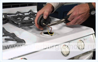
Separately, it is worth stopping at connecting the stove to gas cylinders. This work is often carried out independently, without the involvement of a master. Such a connection has its own nuances. To connect a gas stove to a cylinder, you will need to replace the nozzles in the burners with the same ones, but with a smaller diameter. If the replacement is not made, then the fire begins to smoke heavily. And if natural gas is used for the operation of the equipment, and not liquefied gas, then the flame will be weak and may die out. The rest of the installation process is no different.
Safe Use Rules
To avoid accidents, it is necessary to use the gas stove correctly and have the equipment checked annually. It is important to be careful when operating the equipment:
- Do not leave fire unattended;
- Before opening the faucet, check the gas supply with a match;
- Monitor the health of the ventilation ducts;
- Store cylinders outside living quarters;
- Keep children away from gas equipment.
WATCH VIDEO
The gas oven should also be used carefully. Before starting work, be sure to ventilate for several minutes. After igniting the gas, make sure that the fire burns evenly.
Remember that gas mixed with air is explosive and flammable! If there is a smell of gas in the room, immediately close the gas burners, turn off the tap, open the windows and call the emergency service.
The device of a gas stove only becomes more difficult with time, but the basic principle of operation remains the same. The gas stove functions by burning natural gas. You can connect the stove both to a centralized gas pipeline and to an autonomous source. The gas entering the burner is mixed with oxygen from the atmosphere and this mixture exits through the burner divider, being combustible. After ignition of the gas-air mixture, combustion continues until the gas supply is turned off.
Ignition
Older models of gas stoves are manually ignited. Modern gas stoves are equipped with electric ignition. The device for electric ignition of a gas stove is quite simple. The gas stove is connected additionally to the mains. When the electric ignition button is pressed, the electrical unit generates a spark sufficient to ignite the gas burner. Often, electric ignition is done in such a way that a spark is supplied to all burners, but only the one to which gas is supplied is ignited.
Burners(Gas stove burners)
 The gas stove burner device - the burner consists of a base, a divider and a cover. The burning gas is supplied to the cover of the reflector and from it enters the openings of the divider, creating evenly distributed flames. Burners come in different sizes. In this way, the combustion power is regulated, the larger the burner, the more it can heat. In some models, the gas stove device includes additional electric burners. This can be handy when cooking, as the intensity of heating varies between electric and gas burners, and it's also a very practical option for areas where there are interruptions in the supply of gas and electricity.
Cranes and gas distribution device
 The adjusting cock of the gas stove is built into the gas distribution pipe, when the cock is turned, the gas begins to flow into the burner. Depending on the turn of the tap, the amount of gas entering the burner and the flow of oxygen change, in accordance with this, the flame power on the gas burner changes.
Oven(Oven)
Ovens for gas stoves are - electric, gas or combined with an electric grill.
Gas cabinets are divided into:
Dual-mode oven without fan, gas burner located at the bottom of the oven. Ovens without a fan are often additionally equipped with an electric or gas grill.
Multi-mode oven with fan and forced air circulation. Fan ovens are equipped with special hollow burners that prevent the fan from blowing out the flame.
Gas stove electric ovens come with two heaters on top and bottom, as well as four heaters, one for each wall. Ovens with four heaters are often equipped with a fan to evenly distribute the heated air.
As a rule, the oven is equipped with thermal insulation, which tends to minimize the release of heat to the outside. The oven door has built-in double or triple glass.
Protection system
 The device of new gas stoves is equipped with protection against gas leakage. The combustion sensor is located directly in the burner flame, as soon as it cools down the device shuts off the gas, if it has not been shut off earlier with the burner regulator.
Frame made of enamelled special steel or stainless steel.
Desktop(Hob) is made of stainless enameled steel, tempered impact-resistant glass.
Rules for the production and acceptance of work on gas supply and internal devices, work on maintenance, reconstruction, overhaul and expansion of gas distribution networks, gas consumption and liquefied hydrocarbon gas (LHG) facilities, consumers using gas as fuel, as well as the requirements for the safety of gas supply systems are determined by the requirements SNiP 42-01-2002- "Gas distribution systems", as well as the rules PB 12-609 and OST 153-393-052-2003.
The regulation on the security of gas distribution and gas consumption networks is regulated by federal law from 30.12.2009 No. 384-FZ"Technical regulations on the safety of buildings and structures", as well as the requirements SNiP 2.04.08-8"Gas supply".
Materials and technical products provided for in the projects of gas supply systems must be economical, reliable and comply with the requirements of state standards or technical specifications approved in the prescribed manner and passed state registration in accordance with GOST 2.114-70.
1. The device and operation of burners for gas stoves.
The main task of a gas burner is to convert the chemical energy of the gas into thermal energy. Gas burners must be: reliable in operation, adjustable during operation, stable operation on different modes, stable (long time) when turned on and off; economical in operation.
Gas-burner performs the supply of gas and air to the combustion zone, providing mixture formation, ignition and flame stabilization. General requirements to gas burners is determined by GOST 21204-97.
Regardless of type, all burners have common structural elements:
- gas supply devices ( nozzle) and air ( duct);
- mixer and burner head with stabilizing device.
Widespread classification of burners according to the method of air supply:
- injection- air into which is sucked in due to the energy of the gas jet;
- blastless- the air from which enters the furnace due to rarefaction in it;
- blast- in which air is supplied to the burner or furnace using a fan (with forced air supply).
According to the gas combustion method all burners divided into three groups:
- diffusion burners- without preliminary mixing of gas with air (fig.0-1 pos. "A");
- diffusion-kinetic burners- with complete preliminary mixing of gas with air (fig.0-1 pos. "B");
- kinetic burners- with complete preliminary mixing of gas with air.
In household gas stoves apply injection burners with preliminary mixing of gas with a part of air. gas mixing on the burner with primary and secondary air at work gas stove shown in Fig.1.
Figure 1 shows the methods gas combustion in injection burners used in structures domestic gas stoves.
Only a part of the air necessary for combustion enters the combustion front (Fig. 1, pos. 5), the rest of the air comes from the surrounding space (Fig. 1, pos. 6). These burners work low pressure gas a. They are called injection burners low pressure .
Depending on burner type or operating conditions, its structural elements have a different design. In some burner designs individual elements may be missing or arranged in one part.
2. Cooking burners for gas stoves.
All types of gas stoves equipped with table burners (cooking burners). Placed (1 ... 4 burners) on the upper working surface of the stove (stove table), they are the main body of any gas stove.
In all designs domestic gas stoves used as cooking hobs flame multi-flare injection burners low pressure. The main elements of such burners are:
- nozzle- regulating gas consumption at nominal pressure (nominal heat output of the burner);
- mixer diffuser- where the mixture of the gas leaving the nozzle with the injected primary air takes place (if necessary, the diffuser is supplied with gate device to regulate the access of primary air);
- burner body- a cavity where the mixing of gas with air is completed.
The burner body is equipped with about the upper edge of the fire holes for output of the gas-air mixture to the combustion zone I.
Burner housing (fire nozzle)- usually this is the hollow final part of the mixer, placed coaxially with it or at an angle, depending on the design of the burner and its placement in the stove.
Practice has shown that best results gives a vertical alignment. Hull and firing nozzle at the same time they are performed as a single part.
Slotted fire holes, placed on the upper cut of the cast body, overlap welded steel lid.
Peripheral cover ring collar should provide both flame spread rate, as well as the well-known stabilization - tear protection- due to a portion of the gas-air mixture, retained by the collar at the outlet from the main fire holes.
Device options for stabilization of the flame of gas burners domestic gas stoves are shown in Fig.2.
Flashback protection is achieved by approaching the living sections of fire holes to critical and partial by diverting the mixture through the throttle holes.
Primary air control n at the mixer inlet by using gate with the introduction of stabilizing devices has lost its significance and is not used on a number of modern burner designs.
ATTENTION! Top burners gas stove have the same device and standard dimensions. Differ only stove burners on natural gas and for the operation of plates on liquefied gas.
2.1. Gas burners with end adjustable gate.
On the first models gas stoves, working on artificial gases, primary air control was almost never used. In new designs gas burners created taking into account the use of natural and liquefied gas, have been installed gate devices.
Feature of these burners - two-way secondary air supply- central and peripheral. Scheme gas burner with end adjustable damper- with peripheral and central secondary air supply shown in Fig.3.
The burners have end gate- movable part (fig.3 pos.1) for primary air regulation, bell confuser(fig.3 pos.3) with the fixed part of the gate (fig.3 pos.2) and distributor with a central channel (fig.3 pos.4) and fire nozzle(fig.3 pos.5) - for double-sided secondary air supply.
Primary air regulator(fig.3 pos.1) built into the burner allows regulate the amount in the gas-air mixture.
Burner splitter(fig.3 pos.5) reduces the height of the flame and about facilitates the access of secondary air inside the flame, which contributes completeness of gas combustion. Its body performs the function air/gas mixer.
Burners installed on most older models of domestic gas stoves. The disadvantages of burners are the end location of the gate, to turn it, the burner must be removed from the stove.
2.2. Gas burners with horizontal gate.
This shortcoming has been eliminated in the burners of the St. Petersburg Gas Equipment Plant.
Scheme of a gas hotplate cast burner with horizontal cylindrical or ring gate for natural gas shown in Fig.4.
Burner("Leningradskaya") with cylindrical or ring gate(fig.4 pos.1) primary air placed on the nozzle body(fig.4 pos.3). The burner has replaceable nipple(fig.4 pos.6).
These burners in terms of operational parameters were optimal until 1979, and later they were discontinued.
2.3. Adjustable burners with horizontal tubular mixer.
Based on fire nozzle with top pilot flame have been developed adjustable burners with horizontal tubular mixer.
with horizontal tubular mixer and height adjustable shown in Fig.5.
These burners use primary air suction control by using mouthpiece diffuser(fig.5 pos.1).
A feature of these burners, in addition to the developed length tubular mixer(fig.5 pos.3), is a new way regulation suction of primary air using diffuser mouthpiece. Concerning no longer needed in primary air regulator.
2.4. Burners with horizontal tubular mixer without primary air regulator.
With the introduction of a pilot flame on burners regulation of the primary air with a damper has become practically impractical, because this requires raising the gas stove table every time.
Scheme of a gas unified burner burner with horizontal tubular mixer without regulator primary air is shown in Fig.6.
Instead of gate, regulating the suction of primary air, at the inlet end of the mixing tube(fig.6 pos.3) there are two holes that provide injection required amount primary air. It excludes possibility the appearance of an elongated smoky flame.
Design firing nozzle(fig.6 pos.4) eliminates the possibility of flashover or flame separation.
A requirement was made to the design of the gas stove to reduce potential leaks (during the aging of sealing gaskets) internal gas ducts of the stove transporting gas, which led to the design of burners with a developed tubular mixer(Fig. 6 pos. 3), originating directly from the plate manifold(fig.6 pos.7). it reduced the length gas distribution inside the stove and reduced the number of connections twice.
However, the design of such burners also had a number of disadvantages in manufacturing and worsened the injector ability of the burners, especially for the two rear burners of a 4-burner stove, therefore, starting from 1979. the design of these burners has been discontinued.
2.5. Gas burners with vertical gate.
In universal gas stoves a new model of burners was used - vertical.
Scheme of a gas unified burner burner with vertical cylindrical gate shown in Fig.7.
In these burners nozzle(fig.7 pos.6) and diffuser(fig.7 pos.3) together with fire spreader cap(fig.7 pos.5) are located along one vertical axis.
Burner corps(Fig. 7, pos. 3) are removed through a round hole in the plate table.
design changed fire nozzle(fig.7 pos.4) - burner distributor, which significantly improves secondary air supply to the torches and prevents them from merging.
2.6. Gas burners vertical pilot flame.
Ring flame introduction eliminated the separation of the flame, and a decrease in the width of the slots reduced the chance of flashover. On the basis of the fire nozzle were developed adjustable top pilot flame burners.
Scheme of a gas unified burner burner shown in Fig.8.
Burner inserted into a cylindrical recess corps(Fig. 8, pos. 3) are removed through a round hole in the plate table.
To ensure the completeness of gas combustion design fire nozzle(fig.8 pos.4) - the burner distributor has been changed. fire nozzle done as one piece with mixer and placed vertically along the axis of the nozzle.
Diffuser(Fig. 8 pos. 3) are mounted on shiber mouthpiece(fig.8 pos.1) with gas supply into the burner through the vertical nipple-nozzle(fig.8 pos.6) that significantly improves secondary air supply to the torches and prevents them from merging. The nozzle nipple is fixed on a thread in the body, to which gas is supplied through an aluminum tube.
Feature of these burners, is a new way to regulate primary air intake by using diffuser mouthpiece(fig.8 pos.1). Concerning eliminated the need for a primary air regulator.
2.7. Gas burners vertical burners for higher class stoves.
For high quality slabs a burner developed by the Voronezh Mechanical Plant is used (Fig. 9).
Scheme of a gas unified burner burner with vertical mouthpiece for high quality slabs shown in Fig.9.
Burner It has firing nozzle(fig.9 pos.4) with two rows of firing holes arranged in a checkerboard pattern. Upper row serves to create the main flame, lower - for small stabilizing flame destination.
Mixing part of the burner(fig.9 pos.3) lengthened due to channel continuation in regulator housing(fig.9 pos.1).
Figure 10 shows gas stove table burner manufactured by the French company ENSA, used for gas stoves PG4-P-14 produced by the Brest ZGA.
Scheme of a gas unified burner burner without mouthpiece for high quality slabs shown in Fig.10.
Burner It has firing nozzle(fig.10 pos.4) with round fire holes and ring stabilizing flame posted under the main fire and fed through small holes in the base of the lid(fig.10 pos.5).
3. Burners for ovens floor gas stoves.
Oven or simply oven in floor slabs is their indispensable accessory and is designed to ensure the baking of various dough products, stewing food, frying meat and poultry, etc.
The processes of baking various products, frying and heating food in oven with gas burner flow due to the convective transfer of heat to the flows of hot gas and air combustion products circulating in the cavity of the cabinet.
Design oven gas stove must provide heating of the baked product by the flow of circulating gases from all sides.
For this hearth burner oven placed under its bottom, and the streams of hot combustion products and heated air are directed so that they wash the baking sheet. Thermal power burners of the oven depends on the volume of the oven.
Schemes of circulating streams of hot gases in ovens for old and modern floor tiles are shown in fig.11.
In slab designs In the early models, hot gas flows from the oven were directed to the top of the oven and, washing the walls of the cabinet from the outside, descended to exit through a hole in the side walls of the stove.
Tubular injection burners located on the sides of the oven in front of the viewing windows near the door. Fixed nozzles installed at the back of the oven. Cross-sectional area nozzles of these nozzles and hence throughput more than the nozzles of the upper burners.
Primary air regulators in early designs of ovens installed from the back of the oven, which allows you to adjust the burners in such ovens without the danger of burns to your hands. Currently, gas stoves are produced mainly with fixed burners.
supply gas pipes depart from one crane on the ramp (front panel), so when the crane is opened gas goes directly to both burners of the oven. Device oven tap similar to the device top burner taps.
Holes for secondary air located sides and bottom of the oven, they facilitate the access of secondary air to the flame and the circulation of hot air between the walls of the oven.
Bimetal temperature gauge mounted on top of the oven. When heated, the bimetal spiral begins to rotate, turning the axis with an arrow that indicates the temperature in the oven.
Oven burner options floor standing gas stoves shown in Fig.12.
Burners(Fig. 12 pos. 1-2) were used on old models of Leningrad-made stoves. They were separate installed in parallel on each side of the oven floor, were removable and fed with gas from a common stove gas pipeline and a common tap.
Tubular U-shaped burners(fig.12 pos.3) and stamped burners(Fig. 12 pos. 4) were used for slabs of Moscow production.
Spiral burners(Fig. 12 pos. 5) replaced the twin burners (Fig. 12 pos. 1) on stoves made in Leningrad.
In modern designs top class stoves oven supplied optional frying burner located at the top of the cabinet. Thus, food is processed by a stream of radiant heat directed at it from above.
In high class gas stoves sometimes set second, frying burner"grill", placing it in the upper part of the oven cavity. Sometimes they are installed in ovens burners, in which the radiation source is special metal meshes. On all unified plates of domestic production, disc stamped burners with pilot flame. Disc burners of unified plates are assembled from two stamped discs.
Scheme of a stamped disc burner for ovens floor unified gas stoves shown in Fig.13.
On the bent edge of one of drives (lower) educated rectangular fire holes. Upper disc(fig.13 pos.5) equipped with flanging providing ring stabilizing (pilot) flame located above the fire holes of the burner.
Main burner of the oven plates PG4-II-14 equipped thermocouple and ignition tube. Roast burner, suspended in the top of the oven, equipped with an emitter and an emitter screen.
Roasting burners, built into the oven or installed above the stove, work on the principle thermal or infrared radiation. Here the property is used infrared radiation be absorbed by the surface of the body and even penetrate into the irradiated body to a shallow depth, raising its temperature, the quality of frying increases. That is why for frying meat products it is preferable to use infrared burners.
However, it should be noted that infrared burners provide complete combustion only when operating in an environment with a normal oxygen content, otherwise there is an excessive release of products of incomplete combustion, including carbon monoxide. Consequently, their effective use requires intensive ventilation.
Completeness of gas combustion also requires a good preliminary mixing gas with primary air, sucked in by a gas jet into the inside of the burner, and favorable conditions for secondary air outlet to burner flame.
- However if conditions arise in the combustion zone of gases that lead to to heat removal and combustion zone cooling(for example, the flame washes the metal parts of appliances, heated dishes, etc.), then chemical reactions in these cases may stop, combustible components of the cans do not react with atmospheric oxygen and as a result gas will not burn completely(cm. fig.1- cannot be left without constant supervision).
- Of great importance timely withdrawal from the combustion zone gas combustion products. If they linger in the combustion zone and create an oxygen-poor atmosphere around flame burners, this is lead to deterioration of combustion processes, increase harmful substances in combustion products and possible extinguishing the flame.
- In the same time too intense withdrawal products gas combustion from the combustion zone lead to flame out as a result of high speeds secondary air(see Fig. 1 - must not be left unattended).
NOTE: Gas combustion products come directly into the room, so room ventilation must be under constant control.
Errors in use burners desktop gas stoves shown in Fig.1.
Gas stove burners(single and paired) are an openwork stand that freely passes secondary air to flame gas oven ( primary - comes through gas burner nozzle) and does not interfere with heat transfer when burning gas.
Grid of the table (burner) of the gas stove should provide steady position of dishes with a diameter of at least 120 mm for all burners of a table and utensils with a diameter 60 mm for at least one burner. Steady position of dishes with a diameter 60 mm must be provided by the design of the grate or an additional device (for example, a fire spreader).
For dishes with a wide bottom serve burners with higher ribs, which provide secondary air access to the flame for him stable burning. It should also provide use of utensils, which does not go beyond the table more than 4 cm and so that the distance from its lower edge to the working surface of the table grate can vary from 2 to 8 mm.
NOTE: When using two or more burners distance between the dishes installed on them should be at least 1 cm, otherwise dish size needs to be changed to a smaller diameter.
Subscriber using floor standing gas stove, follows strictly observe the following basic rules for using gas stoves:
- Don `t open cranes on the stove, without cooking lit match.
- Don't leave burning burners without supervision. When the flame goes out turn off the tap on a burnt out fire. Most often extinction can happen with economical combustion.
- Lighting the oven burners through the hatch or using the ignition tube, make sure the gas is on in all fire holes of burners.
- When the flame passes inside the burner immediately switch off her and relight, holding a burning match at the burner's fire holes until the flame stabilizes. If this fails, several reduce by turning the gate primary air access.
- If gas is not supplied to the burner shut off valve, remove the burner and clean(pointed match) nozzle opening.
- With no flame individual firing holes take off burner distributor and clean fire holes.
- Do not bet to normal burners utensils, much larger than them in diameter.. Use a special burner with high ribs(if it is provided for by the design of the plate).
- Before baking preheat the oven within 20…25 min. up to 250°C, bake with a partially closed tap at 150…200°C, fry at full heat output (fully open tap).
- Do not use gas stove like a device for space heating.
- Contain slab in a neat manner. Burners flush in hot soapy water or a weak soda solution. Enamelled surfaces rub with a soft damp cloth.
- Don't contribute into the stove without the help of a gas fitter any fixes or changes.
When using a gas stove the flame must be even over the entire fire surface, do not have yellow tongues and should be resistant to air flow.
Operation of gas stove burners with too much or too little air in the room shown in Fig.2.
Flame break- a phenomenon in which the flame is partially or completely detached from the outlets of the burner. A slight separation of the flame is allowed for 1 min. after ignition, or switch the burner tap to low flame. Flame separation is allowed at the moment of ignition, if combustion stability is established later.
Flashlight- a phenomenon characterized by the movement of the flame inside the burner (in its mixing part).
yellow tongues- a phenomenon characterized by the appearance of yellow-colored flames caused by incomplete combustion of gas. Yellow tongues of flame are allowed within 10 minutes after the installation of the vessel with cold water if there is no soot deposition.
flame stability- the property of the flame to be stably held on the outlets of the burner without separation or breakthrough of the flame into the burner.
2. Types of household gas stoves.
By installation method domestic gas stoves are divided into floor and desktop, and by design - into plates of the main design and increased comfort. In the main version issued:
- stoves with two, three or four burners table and oven for work on natural or liquefied gases;
- and with three table burners, oven and a cabinet for installing a cylinder with liquefied gas.
Plates classify not only by the number of table burners, but according to their place of installation:
- floor gas stoves(including with built-in gas bottle):
- desktop.
If possible layouts with kitchen furniture: embedded; free standing. By the presence of the oven: with oven and without oven.
depending from applied gases plates can be three performances:
- for work on gases of the same class;
- for work on gases of two classes;
- for work on gases of three classes.
By way conversion of stoves to gas another class or group:
- by adjusting filing primary air and adjustments gas flow(in the presence of a pressure regulator);
- by replacing adjusting ( replacement parts, for example nozzles.
Plates are produced for work on natural gas with nominal pressure 1.3 and 2 kPa and liquefied petroleum gas with nominal pressure 3 kPa. Slab translation for work on other gas can be done only with removable nozzles.
Various types of gas stoves, having a common technological scheme, differ in the number of burners, the device of the oven and their burners, thermal power and some other design features. Some of them are presented in this section.
Some of these modifications were taken into production by the Voronezh Mechanical Plant ( PG4-P-02 and PG4-P-03 (4K1a)), Leningrad EZGA ( PG4-P-02) and Brest ZGA ( PG4-P-14).
GOST 10798-85* provided in the classification of plates of the model of the highest class B, subdividing them into groups "a" and "b". Plates of class B "a" must include a full set of automatic devices and have the comfort conditions provided for foreign analogues of the "Lux" class. Models of class B "b" provided for the partial use of the full set. A number of such models, conditionally named " comfort slabs", was introduced into the framework of special specifications.
A. Household gas stove PG-4.
have the greatest application plates type PG-4- 4-burner gas stove. Four-burner stoves in the form of cabinets with doors for frying and drying cabinets. A viewing window is built into the oven door.
Plate table PG-4 also serves as a tray to collect spilled food. burner grids- bar, enameled or oxidized. Oven is an all-welded structure with a removable bottom and hangers for three shelves. Disc burner does not have an igniter and is ignited through a hinged hatch at the bottom of the oven.
Device diagram household gas stove type PG-4 shown in Fig.4.
On the slab frame from enameled steel (Fig. 4, pos. 1) all equipment is fixed and placed. Table(fig.4 pos.2) gas stove with drip tray made of enamelled steel, fixed tightly to the frame or movably hinged so that it can be folded away, facilitating access to gas burners. Removable burner grids made of bar steel.
Gas burner taps mounted on the collector with the withdrawal of handles (Fig. 4 pos. 10) on distribution panel(Fig.4 pos.3) gas stove and serve to switch the gas supply, as well as to regulate its consumption. The faucet handle is made of non-conductive plastics and is attached to the faucet plug.
Ramp or the front distribution panel (fig.4 pos.3) consists of a cover attached to the plate frame with two screws. Under the cover is a distribution tube with five taps. Faucet handles(Fig. 4 pos. 10-11) put on tap plugs after the panel board is installed.
Injection burner(fig.4 pos.15) is located under the bottom of the oven. Cross-sectional area nozzles(fig.4 pos.14) lower burner nozzles larger and, therefore, the throughput is greater than the nozzles of the upper burners. That's why at work oven burners, turn on top burners table is NOT RECOMMENDED.
Secondary air hole located bottom of the oven, it facilitates the access of secondary air to the flame and hot air circulation between oven walls.
Bimetal temperature gauge(fig.4 pos.12) mounted on the top behind the oven glass(fig.4 pos.5). When heated, the bimetal spiral begins to rotate, turning the axis of the arrow, which shows oven temperature.
oven protected by a heat-insulating layer of slag wool. Under the oven located drying cabinet(fig.4 pos.6). The oven kit includes wire rack, roaster and baking sheet.
B. Household gas stoves of increased comfort.
From domestic gas stoves superior comfort have the greatest application plates of type PG-4-P-14(Brest ZGA) - 4-burner gas stove. The stove is characterized by increased comfort, high technical level design and good performance. Temperature regime plate walls allows you to integrate it into kitchen sets.
Device diagram household gas stove type PG-4-P-14 superior comfort shown in Fig.5.
In the plate body built-in oven (Fig.5 pos.17) and drying (Fig.5 pos.6) cabinets. In the stove oven installed two burners: main - lower (Fig. 5, pos. 18) and additional frying - upper (Fig. 5, pos. 16).
Maintenance of the set mode burning oven burners performed using special automatic devices.
On the left side switchboard or panels(fig.5 pos.3) is located button(fig.5 pos.12) thermostatic tap(fig.5 pos.11), consisting of (fig.5 pos.13) and thermostat(fig.5 pos.14).
These devices provide a safe working environment and automatic gas supply control to the main oven burner.
thermostat provides temperature maintenance in the oven at the given level. Thermo solenoid valve controls the presence of a flame on the main and frying burners oven and stops gas supply when they go out.
First, the gas enters from the manifold into the thermo solenoid valve, and then if there is a passage into the thermostat. Simultaneous operation the main and frying burners of the oven excluded due to blocking thermo-static faucet.
Gas passage possible only after ignition basic(fig.5 pos.18) or fryer(fig.5 pos.16) oven burners.
Work of burners of domestic gas stoves will be discussed in the following sections of the site. See below for a more detailed diagram of the internal gas pipeline of the stove.
3. Internal manifold of the gas stove.
Under the stove pipeline imply gas communications from the connecting part of the collector to the fire holes burner device, including all pipe branches to individual burners or automation elements, the automation elements themselves (if provided), taps, nozzles, and finally, gas-burners.
All this set of parts and assemblies should be subordinated to one main task - gas transportation within the apparatus without any leaks.
Internal device of the gas stove consists of a collector ( internal gas pipeline) curved at an angle of 90°. At the point of connection to intra-apartment gas pipeline plate manifold equipped with a strainer(fig.6 pos.33).
Cranes(fig.7 pos.15…16) and gas mixers(fig.6 pos.29 and fig.7 pos.3) have threaded ends under the union nuts of the adjustable gas pipes (Fig. 7, pos. 6). Cranes installed on gas manifold plate with clamping flanges.
Schemes of the internal gas pipeline of the stove superior comfort PG-4-P-14 (Brestskaya) shown in Fig.6 and Fig.7.
Scheme of the internal gas pipeline of the slab of increased comfort PG-4-P-14 (Brestskaya).
1- plate body; 2- thermocouple of the main burner; 3 - the main burner of the oven; 4- burner nozzle; 5- body of the burner nozzle; 6- internal gas pipeline of the stove; 7- side wall of the oven; 8- thermal insulation of the oven; 9- protective screen for thermal insulation of the oven; 10- lampshade for lighting the oven; 11- gas pipeline of the upper frying burner; 12 - support fastening of the upper burner; 13- button of the thermo-electromagnetic valve of the oven; 14 - decorative panel of the stove; 15- handle of the thermostatic valve of the oven; 16- handles of the taps of the upper burners of the stove; 17- thermocouple of the frying burner; 18- frying burner (upper) of the oven; 19 - lower door of the drying cabinet; 20- ignition tube of the lower burner of the oven; 21- oven door spring; 22- oven door pull; 23- thermal insulation of the oven door; 24 - removable oven roaster; 25- oven grill for frying; 26 - oven sight glass; 27- plate table cover; 28- grate over the burners of the stove table; 29- gas burners of the table; 30 - traverse; 31 - protective screen burners; 32- table bracket; 33- filter; 34 - stiffening element of the gas pipeline of the table; 35- reflector; 36- chimney of the oven.
Pipelines on gas stoves old models were made from steel pipes d=1/2"(for plate manifold) and d=10…12 mm (for burner pipes and gas pipeline of the oven) with a protective coating of galvanized galvanizing or enameling.
In modern designs unified plates gas pipelines, from manifold to burners, made of aluminum pipes d=10…12 mm.
Connections segments of individual pipes between themselves, with taps and with burners on all domestic plate designs old models threaded; either with couplings and lock nuts, or with direct mutual make-up (for connections with valves) and a lock nut.
The disadvantage of such compounds- the relative complexity of creating their reliable sealing. Requires very precise threading, sealing threaded connection tow impregnated with heat-resistant varnish, proper tightening of the lock nut and a thorough check of the assembled unit for tightness.
Wherein yet possible gas leaks arising due to loosening of the connection during installation or drying of the sealing material. In this regard, when putting the gas stove into operation and at each routine inspection leak test required and as needed sealing gas leaks.
Data work may only be carried out gas industry specialist who has a permit for the repair and adjustment of gas equipment.
ATTENTION! Simultaneous gas supply on the main and frying oven burners NOT ALLOWED.
At the junctions constituent parts burners gas-air mixture leakage NOT ALLOWED. When a gas leak is detected necessary turn off the gas appliance immediately and notify the emergency gas service.
4. Automatic devices of gas stoves.
Ease of gas stove control- the absolute advantage of a household gas stove. The undesirable excessive rise in the cost of gas stoves installed in residential buildings made it possible to include only the most necessary automation devices in the modification of stoves.
Among the indicated minimum built-in automatic units relate:
- electric ignition- device for automatic ignition of burners;
- shut-off valves- security automation:
- oven temperature control;
- mechanical electric spit rotation and etc.
Construction of gas stoves provides the possibility of visual control of the presence of the flame of the burners of the oven in the absence of a safety device.
Floor slab construction allows the removal of each faucet, thermostat and safety device without removing the manifold.
Cookers equipped with a safety device and/or thermostat, must have a gas filter.
4.1. Ignition device.
Ignition device, if present, may be electric or piezo ignition and should provide fast and reliable ignition.
All constituent elements ignition devices must be designed so that avoid damage or accidental displacement. Device position ignition and burners in relation to each other must be unchanged.
ATTENTION! If the ignition device every time gives only one spark, then the device is activated no more than 3 times- with an interval of 1 sec. Upon failure ignition devices must be able to light each burner with a match.
If necessary, restart oven burners a, wind cabinet is pre-ventilated cooling down to room temperature.
4.1.1. Electric ignition.
Automatic ignition of stove burners carried out two ways- piezoelectric (piezo ignition) and electric spark.
A. Piezo ignition system.
The principle of operation of the piezo ignition is based on the use of the effect of generating high-voltage pulses of short duration - the piezoelectric effect.
Device, shown in Fig. 8, can be used for any gas appliance by linking its trigger valve or others with the trigger mechanism of the piezoelectric device.
Device diagram piezo ignition burner household gas stove shown in Fig.8.
Piezo ignition device consists from the housing (Fig.8 pos.8), in which two piezoelectric elements (Fig.8 pos.1) with an insulating clip (Fig.8 pos.3) and a high-voltage output (Fig.8 pos.2) are placed.
In case(Fig.8 pos.8) a spring-loaded striker is installed (Fig.8 pos.6). The spring (Fig. 8 pos. 7) is charged through the rod (Fig. 8 pos. 9) when the plate valve handle is turned to the closed position. When you open a faucet the striker hits the end of the piezoelectric element, causing an impulse sufficient to produce a spark in the arrester placed opposite the burner's fire hole.
If present in the burner stabilizing annular flame, the sparking point is oriented only in height.
B. Electric spark ignition of the stove.
Electric spark ignition plates can be carried out according to various electrical circuits.
Ignition performed by pressing electric ignition buttons before opening the burner tap. spark used on the burner whose faucet in this moment open to gas.
4.2. Burner flame control device.
If available device for flame control, then it should provide automatic termination gas supply when the burner flame goes out no more than 90 sec.
During operation device when the burner is switched on must be no more 30 sec.
Sensor element devices for flame control must control one burner. The burner is switched on manually.
Device design flame control must ensure the termination of the supply gas to burner when element sensitivity fails.
4.2.1. Burning automation.
Flame cutoff solenoid valve (EMC) applied to control the presence of a flame on the burner. In case of flame out introduced into the flame zone thermocouple(fig.5 pos.15) cools down. Wherein valve(fig.5 pos.13), not held by an electromagnet, under the influence of a spring interrupts the gas supply to the heater.
Such safety devices used on burners stove tables and in ovens of gas stoves. For oven burners such valve installed in mass-produced plates PG4-P-14 Brest ZGA, where it is assembled in a common node (Fig. 5, pos. 12-13) with thermostat(fig.5 pos.14) main burner oven(fig.5 pos.17).
Automation is adjusted to the required mode of operation when it is released by the manufacturer and does not require additional adjustment.
However, during transportation there may be some confusion, it mainly concerns thermo solenoid valve(fig.5 pos.13), where it is important to keep a fixed position hot junction thermocouple(fig.5 pos.15) at the holes main burner oven.
If a after pressing buttons(fig.5 pos.12) and burner ignition(fig.5 pos.18) release the button and after that after 30-40 sec. the flame goes out, which means that there is a problem in the EMC system.
Valve failure may be caused:
- weak pressure buttons(fig.5 pos.12);
- displacement thermocouples(Fig. 5, pos. 15) relative to the fire hole (for the main burner) and its poor heating with a flame;
- contact oxidation thermocouples and EMC.
NOTE: To eliminate the failure of the EMC when putting the slab into operation (or during operation), you need to call the gas master.
In high class boards faucet-valve(fig.5 pos.11), used for combustion control on table burners, installed for each burner separately and has a separate thermocouple.
With axial pressure and turning the faucet handle gas burner the valve is pressed, opening access gas through the valve to the burner. After ignition(manual or automatic) thermocouple burners(fig.5 pos.15) heats up and holds valve(fig.5 pos.13) gas supply open.
When the faucet is closed or burner emergency shutdown thermocouple cools down and the valve shuts off the gas supply to the burner.
All of the above works for adjustment and repair of automatic cooker generally must be carried out by experts territorial gas facilities when installing the stove and during its operation according to your request.
For this purpose manufacturer for the warranty period provides gas facilities spare parts is free, and then delivers them on demand.
5. Maintenance of household gas stoves.
All stationary operated gas stoves are registered from local gas operating organizations and constantly served by them.
For gas stoves exist the following types of maintenance:
- annual scheduled maintenance (GPR);
- intermediate maintenance (PTO);
- unscheduled repairs at the request of gas consumers (VRZ).
Annual scheduled maintenance (GPR)- the main type of maintenance of in-house gas equipment of residential buildings and public buildings. It includes a set of mandatory works that ensure reliable and safe operation of in-house gas equipment for a period of at least 1 year.
Intermediate maintenance (PTO)- maintenance of in-house gas equipment is necessary in public buildings and communal apartments, where, due to intensive operation and frequent changes (or a large number) of consumers, it is impossible to ensure reliable and safe operation of gas equipment by carrying out only HPR. In the process of PTO, the operability of gas equipment is checked, and the detected malfunctions are eliminated.
Unscheduled repair (VRZ)- performed on the basis of requests from subscribers (gas consumers). During the VRZ, the malfunctions indicated in the application are eliminated and the operability of the repaired gas equipment is checked.
At each maintenance of the in-house gas equipment, a instructing subscribers on the safety rules for using gas.
Unauthorized or unusable for further operation gas equipment, as well as devices with the removal of combustion products in a chimney with no draft, should be switched off.
In case of violation consumer rules safe use of gas gas utility has the right to turn off household gas appliances.
Responsibility for condition and correct operation domestic gas equipment and gas pipelines in cities and towns are borne by operating organizations of gas facilities.
Departmental and private houses served relevant house administrations (ZHEK), operating organizations of gas facilities under contracts with him or the owners of houses.
The main form of service gas equipment of a residential building is a periodic preventive inspection and repair of gas appliances and an intra-house gas pipeline, carried out in a planned manner and at the request of consumers.
The following periodicity is established preventive inspections in residential buildings:
- control pressing gas pipelines carried out - 1 time in 5 years,
- timing of preventive examinations house gas pipelines established by gas authorities - in agreement with Gosgortekhnadzor,
- Maintenance produced - 1 time per year,
- lubrication of taps and repacking of stuffing boxes on risers and inlets - 1 time per year,
- instrument faucet lubrication - during prophylaxis.
Preventive inspection of gas stoves and fast water heaters produce - 1 time in 2 months.
Storage water heaters, heating, heating and cooking furnaces and other devices having an automatic device, are examined - 1 time per month.
During a preventive examination, without fail, performed the following works:
- inspection all gas pipelines, starting from the valve at the input,
- washing all connections to check the condition and tightness connections and fittings on the gas pipeline at each scheduled visit;
- lubricant cranes at the input, branches to apartments and to risers as needed;
- examination fasteners on the gas pipeline on every visit on schedule;
- work check fittings for gas appliances - 1 time in 3 months;
- withdrawal burners and cleaning nozzles - as needed;
- examination connection density on every visit on schedule;
- adjustment all stove burners - as needed;
- examination serviceability of block crane automation and automation security for instantaneous water heaters - on schedule;
- regulation water and gas supply with work check water heater in different modes on schedule.
All indoor equipment subject to maintenance in accordance with production instructions and schedules.
Works on TO VDGO are carried out in strict accordance with the Rules for technical operation and safety requirements in the gas industry of the Russian Federation and SNiP. Maintenance procedure and terms are established by gas facilities enterprises and agreed with gas consumers (ZHEU, DEU, etc.). Wherein first maintenance produced after 6 months after expiration of the warranty period for gas appliances in operation.
Gas stoves offered to the buyer today are significantly different from those that were in apartments in Soviet times. They have not only a new design, but also completely different technical characteristics. Their range is so large that, without knowing all the nuances, to carry out right choice very difficult. After studying all the elements that a gas stove is equipped with, it is not difficult to buy + in Nizhny Novgorod this heating device.
Principle of operation
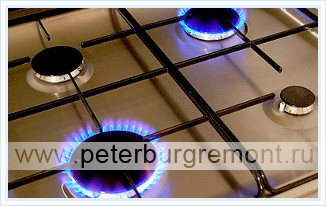
The stove works with natural gas. It can be used both supplied through the city network and bottled. Increasing or decreasing the flame is done by adjusting the flow that is supplied to gas burner. During passage through the nozzle, it mixes with air, which leads to the formation of a gas-air mixture. There are holes on the side of the divider through which this mixture exits and ignites.
Burning gas
What else do you need to know about this heating device how gas stove burning ? Gas combustion is exactly the process in which the operation of gas heating equipment consists. Installed on slabs atmospheric burners. They do not have a special outlet where the combustion products would go. Therefore, they are thrown into the room where the stove is installed. The combustion process uses air from the burner nozzles and air from environment. The dishes are heated with the help of combustion products coming out of the heaters. Rising along the walls, they carry out heating and rise into the air. High-quality design contributes to the complete combustion of gas.
Device
Plates have the following main elements:
- Frame.
- Desktop.
- Burners.
- Oven.
- Gas distribution device with taps.
- Thermostat.
- Electric piezo lighter.
Burners
Nozzles play the most important role in burners. With their help, the gas-air mixture is supplied to the surface. Their holes are different diameter. Burners are installed at a distance of at least 230 mm from each other.
hob
In most cases, gas stoves have hobs made of enamelled stainless steel. Stainless steel is very practical. It has a high chemical resistance. There is an exquisite gas stove, which you can buy in Nizhny Novgorod both on the Internet and in a special store. Its hob is made of tempered glass, which features impact resistance and durability.
Oven
Standard gas ovens are divided into two types:
- With dual-mode heating without fan;
- With multi-mode heating and forced air circulation.
In the first version, the gas heater is located at the bottom of the oven. An additional grill burner can be installed in the upper part. In the second version, the ovens are equipped with four heating elements located below, above, at the back wall and on the side.
__________________________________________________