
The number of Gcal per 1 square meter standard. Calculation of thermal energy for heating
Hello dear friends! In today's article, I would like to consider the calculation of the need for heat (heating) by the months of the year. This article is about how to calculate the annual heat demand, broken down by months, to heat your home, building, etc. I would like to emphasize right away that we are talking about heating, hot water supply is not calculated in the calculation. For the calculation, we need initial data. In the heat supply contract with the energy supplying organization, you must specify the heat load for heating: Qheat, Gcal/h. Let in our case it will be Qgcal = 0.036 Gcal/h.
Also, to calculate the need for heat energy for heating by year, we need: tin, indoor temperature in the room, ° С; tcalc., design temperature for heating, °C. Let's take for calculation: tin = 20 °С, tcalc = -43 °С (for Bratsk). The temperature tvn = 20 ° С is the standard temperature for rooms in buildings (not corner ones), the design temperature for heating tcalc in degrees ° С is taken from SNiP 23-01-99 "Construction climatology" for your city. In addition, from this SNiP we will need the average monthly outdoor temperature tout.air for your city. In our case, t outside air = -20.7 ° С for the city of Bratsk, January. So, we have all the data, we can make a calculation.
The amount of heat demand for heating by month is calculated as follows:
Qmonth \u003d Qheat * (tin-tout. air) / (tin-tcalc) * number of hours in a month.
Let's look at a specific example. Take January, the amount of heat demand in this case will be equal to:
Qmonth \u003d 0.036 * (20- (-20.7)) / (20- (-43)) * 744 \u003d 17.3 Gcal
Of course, if there is a heat meter, this calculation is not so interesting. After all, in this case, in any case, you pay according to the readings of the device for the actually consumed heat. But if you do not have a thermal energy meter, or it is out of order, then the knowledge and application of this calculation will come in handy. Useful for checking the numbers in Gcal for heating in the annex to the heat supply agreement. This application is usually called - the planned amount of thermal energy for heating at the subscriber. Or another option is to calculate the need for thermal energy for heating the consumer.
In villages and small towns, where there are small heating loads Qotop at the facilities, and there are no heat meters (it happens that there is not even a metering at the source of heat supply - the boiler house), the amount of heat consumed for heating is calculated exactly like this, according to this method. Only d for more accurate calculation in the calculation formula, instead of the SNiP average monthly temperature, the actual average monthly temperature of the outside air is substituted. But this is for objects where there is no heat meter either at the consumer, or at the central heating station, or even at the heat source. I have several such objects, in the villages.
In a city, usually, if there is no metering device, or it is temporarily out of order, the amount of consumed heat energy is set by the energy supply organization using a slightly different method. This is the so-called balance, or "boiler" method. But that is another topic.
My calculation of heat demand for heating by year, broken down by months, which I did for one of my objects, can be downloaded here:
I will be glad to comments on the article
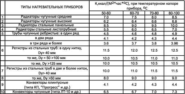
The thermal calculation method is the determination of the surface area of each individual heater which releases heat into the room. The calculation of thermal energy for heating in this case takes into account maximum level coolant temperature, which is intended for those heating elements, for which the heat engineering calculation of the heating system is carried out. That is, if the coolant is water, then its average temperature is taken in heating system. In this case, the flow rate of the coolant is taken into account. Similarly, if the heat carrier is steam, then the calculation of heat for heating uses the value highest temperature steam at a certain pressure level in the heater.
Method of calculation
To calculate the heat energy for heating, it is necessary to take the heat demand indicators of a separate room. In this case, the heat transfer of the heat pipe, which is located in this room, should be subtracted from the data.
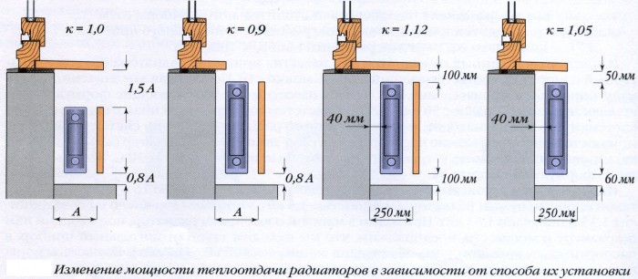
The surface area that gives off heat will depend on several factors - first of all, on the type of device used, on the principle of connecting it to pipes and on how exactly it is located in the room. It should be noted that all these parameters also affect the density of the heat flux coming from the device.
Calculation of heaters of the heating system - the heat output of the heater Q can be determined by the following formula:
Q pr \u003d q pr * A p.
However, it can be used only if the indicator of the surface density of the thermal device q pr (W / m 2) is known.
From here it is also possible to calculate the estimated area A p. It is important to understand that the calculated area of any heating device does not depend on the type of coolant.
A p \u003d Q np / q np,
in which Q np is the level of heat transfer of the device required for a certain room.
The thermal calculation of heating takes into account that the formula is used to determine the heat transfer of the device for a certain room:
Q pp = Q p - µ tr *Q tr
while the indicator Q p is the heat demand of the room, Q tr is the total heat transfer of all elements of the heating system located in the room. The calculation of the heat load for heating implies that this includes not only the radiator, but also the pipes that are connected to it, and the transit heat pipe (if any). In this formula, µ tr is the correction factor that provides for the partial heat transfer of the system, designed to maintain a constant temperature in the room. In this case, the size of the amendment may vary depending on how exactly the pipes of the heating system were laid in the room. In particular - with the open method - 0.9; in the furrow of the wall - 0.5; embedded in a concrete wall - 1.8.
The calculation of the required heating power, that is, the total heat transfer (Q tr - W) of all elements of the heating system is determined using the following formula:
Q tr = µk tr *µ*d n *l*(t g - t c)
In it, k tr is an indicator of the heat transfer coefficient of a certain segment of the pipeline located in the room, d n is the outer diameter of the pipe, l is the length of the segment. Indicators t g and t in show the temperature of the coolant and air in the room.
Formula Q tr \u003d q in * l in + q g * l g used to determine the level of heat transfer of the heat pipe present in the room. To determine the indicators, refer to the special reference literature. In it you can find the definition of the thermal power of the heating system - the definition of heat transfer vertically (q in) and horizontally (q g) of a heat pipeline laid in the room. The data found show the heat transfer of 1m of pipe.
Before calculating Gcal for heating, for many years, calculations made using the formula A p = Q np / q np and measurements of the heat-releasing surfaces of the heating system were carried out using a conventional unit - equivalent square meters. At the same time, ekm was conditionally equal to the surface of the heating device with a heat transfer of 435 kcal/h (506 W). The calculation of Gcal for heating assumes that in this case the temperature difference between the coolant and the air (t g - t in) in the room was 64.5 ° C, and the relative water flow in the system was equal to G rel = l.0.
Calculation of heat loads for heating implies that at the same time, smooth-tube and panel heaters, which had a greater heat transfer than the reference radiators of the times of the USSR, had an area of ekm, which differed significantly from their physical area. Accordingly, the area of less efficient heaters was significantly lower than their physical area.
However, such a dual measurement of the area of \u200b\u200bheating devices in 1984 was simplified, and the ekm was canceled. Thus, from that moment on, the area of the heating device was measured only in m 2.
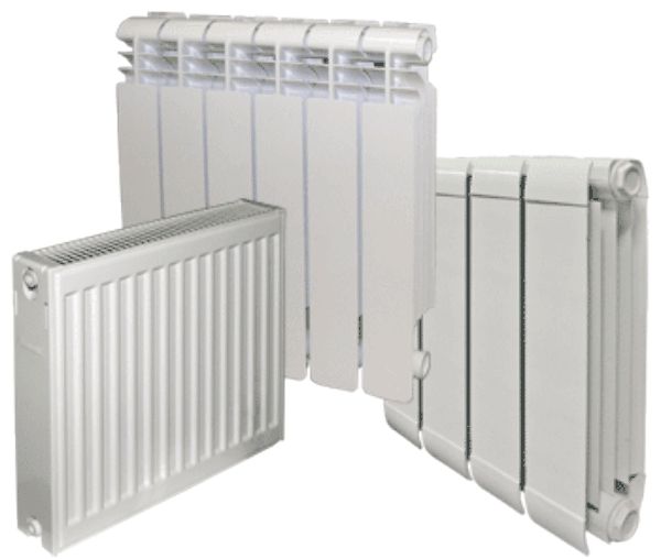
After the area of the heater required for the room and the calculation of the heat output of the heating system are calculated, you can proceed to the selection of the necessary radiator according to the catalog of heating elements.
It turns out that most often the area of the purchased element is somewhat larger than that which was obtained by calculation. This is quite easy to explain - after all, such a correction is taken into account in advance by introducing a multiplying factor µ 1 into the formulas.
Today, sectional radiators are very common. Their length directly depends on the number of sections used. In order to calculate the amount of heat for heating - that is, to calculate the optimal number of sections for a particular room, the formula is used:
N = (Ap /a 1)(µ 4 / µ 3)
In it, a 1 is the area of \u200b\u200bone section of the radiator selected for installation in the room. Measured in m 2. µ 4 is the correction factor that is applied to the method of installing the heating radiator. µ 3 - correction factor, which indicates the actual number of sections in the radiator (µ 3 - 1.0, provided that A p \u003d 2.0 m 2). For standard M-140 type radiators, this parameter is determined by the formula:
µ 3 \u003d 0.97 + 0.06 / A p
During thermal tests, standard radiators are used, consisting of an average of 7-8 sections. That is, the calculation of heat consumption for heating determined by us - that is, the heat transfer coefficient, is real only for radiators of just this size.
It should be noted that when using radiators with a smaller number of sections, a slight increase in the level of heat transfer is observed.
This is due to the fact that in the extreme sections the heat flow is somewhat more active. In addition, the open ends of the radiator contribute to greater heat transfer to the room air. If the number of sections is greater, there is a weakening of the current in the extreme sections. Accordingly, to achieve the required level of heat transfer, the most rational is a slight increase in the length of the radiator by adding sections, which will not affect the power of the heating system.
For those radiators, the area of one section of which is 0.25 m 2, there is a formula for determining the coefficient µ 3:
µ 3 \u003d 0.92 + 0.16 / A p
But it should be borne in mind that it is extremely rare when using this formula, an integer number of sections is obtained. Most often, the desired amount is fractional. Calculation heating appliances heating system assumes that in order to obtain a more accurate result, a slight (no more than 5%) decrease in the A p coefficient is acceptable. This action leads to limiting the level of deviation of the temperature indicator in the room. When the calculation of heat for space heating is made, after receiving the result, a radiator is installed with the number of sections as close as possible to the obtained value.
The calculation of heating power by area assumes that certain conditions the architecture of the house also imposes on the installation of radiators.
In particular, if there is an external niche under the window, then the length of the radiator must be less than the length of the niche - not less than 0.4 m. This condition is valid only with a direct pipe connection to the radiator. If a duckbill connection is used, the difference between the length of the niche and the radiator should be at least 0.6 m. In this case, the extra sections should be separated as a separate radiator.
For individual models of radiators, the formula for calculating heat for heating - that is, determining the length - does not apply, since this parameter is predetermined by the manufacturer. This fully applies to radiators such as RSV or RSG. However, it is not uncommon for cases when, to increase the area of \u200b\u200ba heating device of this type, simply parallel installation of two panels side by side is used.
If a panel radiator is defined as the only one allowed for a given room, then to determine the number of required radiators, the following is used:
N \u003d Ap / a 1.
In this case, the radiator area is a known parameter. If two parallel blocks of radiators are installed, the A p indicator is increased, determining the reduced heat transfer coefficient.
In the case of using convectors with a casing, the calculation of the heating output takes into account that their length is also determined exclusively by the existing model range. In particular, the floor convector "Rhythm" is presented in two models with a casing length of 1 m and 1.5 m. Wall convectors may also slightly differ from each other.
In the case of using a convector without a casing, there is a formula that helps to determine the number of elements of the device, after which it is possible to calculate the power of the heating system:
N \u003d A p / (n * a 1)
Here n is the number of rows and tiers of elements that make up the area of the convector. In this case, a 1 is the area of one pipe or element. At the same time, when determining the calculated area of the convector, it is necessary to take into account not only the number of its elements, but also the method of their connection.
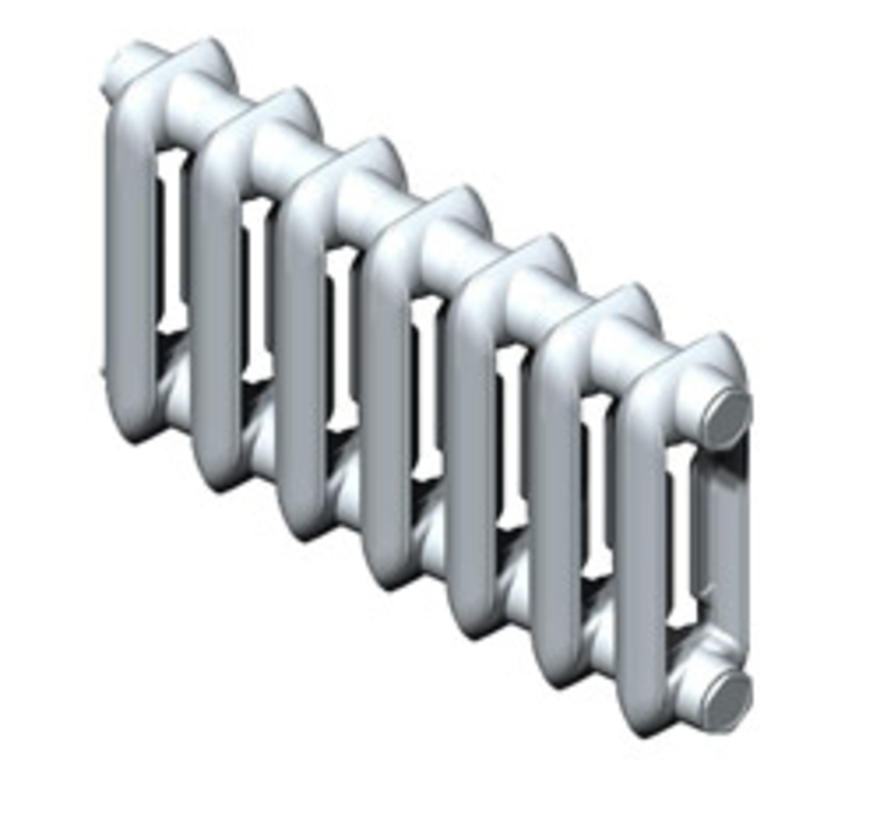
If a smooth-tube device is used in the heating system, the duration of its heating pipe is calculated as follows:
l \u003d A p * µ 4 / (n * a 1)
µ 4 is the correction factor that is introduced in the presence of a decorative pipe cover; n is the number of rows or tiers of heating pipes; and 1 is a parameter characterizing the area of one meter of a horizontal pipe with a predetermined diameter.
To obtain a more accurate (rather than a fractional number), a slight (no more than 0.1 m 2 or 5%) decrease in A is allowed.
Example #1
It is necessary to determine the correct number of sections for the M140-A radiator, which will be installed in the room located on the top floor. At the same time, the wall is external, there is no niche under the windowsill. And the distance from it to the radiator is only 4 cm. The height of the room is 2.7 m. Q n \u003d 1410 W, and t in \u003d 18 ° С. Radiator connection conditions: connection to a single-pipe riser of a flow-controlled type (D y 20, KRT tap with 0.4 m inlet); the wiring of the heating system is upper, t g \u003d 105 ° C, and the coolant flow through the riser is G st \u003d 300 kg / h. The difference between the temperature of the coolant of the supply riser and the one under consideration is 2 ° C.
Determine the average temperature in the radiator:
t cf \u003d (105 - 2) - 0.5x1410x1.06x1.02x3.6 / (4.187x300) \u003d 100.8 ° С.
Based on the data obtained, we calculate the density heat flow:
t cf \u003d 100.8 - 18 \u003d 82.8 ° С
At the same time, it should be noted that there was a slight change in the level of water consumption (360 to 300 kg/h). This parameter has practically no effect on q np .
Q pr \u003d 650 (82.8 / 70) 1 + 0.3 \u003d 809 W / m2.
Next, we determine the level of heat transfer horizontally (1r \u003d 0.8 m) and vertically (1v \u003d 2.7 - 0.5 \u003d 2.2 m) located pipes. To do this, use the formula Q tr \u003d q in xl in + q g xl g.
We get:
Q tr \u003d 93x2.2 + 115x0.8 \u003d 296 watts.
We calculate the area of the required radiator according to the formula A p \u003d Q np / q np and Q pp \u003d Q p - µ tr xQ tr:
And p \u003d (1410-0.9x296) / 809 \u003d 1.41m 2.
We calculate the required number of sections of the M140-A radiator, given that the area of one section is 0.254 m 2:
m 2 (µ4 = 1.05, µ 3 \u003d 0.97 + 0.06 / 1.41 \u003d 1.01, we use the formula µ 3 \u003d 0.97 + 0.06 / A p and determine:
N \u003d (1.41 / 0.254) x (1.05 / 1.01) \u003d 5.8.
That is, the calculation of heat consumption for heating showed that in order to achieve the most comfortable temperature, a radiator consisting of 6 sections should be installed in the room.
Example #2
It is necessary to determine the brand of an open wall-mounted convector with a casing KN-20k "Universal-20", which is installed on a single-pipe flow-type riser. There is no crane near the installed device.
Determines the average water temperature in the convector:
tcp \u003d (105 - 2) - 0.5x1410x1.04x1.02x3.6 / (4.187x300) \u003d 100.9 ° C.
In "Universal-20" convectors, the heat flux density is 357 W/m 2 . Available data: µt cp =100.9-18=82.9°С, Gnp=300kg/h. According to the formula q pr \u003d q nom (µ t cf / 70) 1 + n (G pr / 360) p recalculate the data:
q np \u003d 357 (82.9 / 70) 1 + 0.3 (300 / 360) 0.07 \u003d 439 W / m 2.
We determine the level of heat transfer of horizontal (1 g - \u003d 0.8 m) and vertical (l in \u003d 2.7 m) pipes (taking into account D y 20) using the formula Q tr \u003d q in xl in + q g xl g. We get:
Q tr \u003d 93x2.7 + 115x0.8 \u003d 343 watts.
Using the formula A p \u003d Q np / q np and Q pp \u003d Q p - µ tr xQ tr, we determine the estimated area of the convector:
And p \u003d (1410 - 0.9x343) / 439 \u003d 2.51 m 2.
That is, the convector "Universal-20" was accepted for installation, the length of the casing of which is 0.845 m (model KN 230-0.918, the area of \u200b\u200bwhich is 2.57 m 2).
Example #3
For system steam heating it is necessary to determine the number and length of cast iron finned tubes, provided that the installation open type and is produced in two tiers. In this case, the excess steam pressure is 0.02 MPa.
Additional characteristics: t nac \u003d 104.25 ° С, t v \u003d 15 ° С, Q p \u003d 6500 W, Q tr \u003d 350 W.
Using the formula µ t n \u003d t us - t in, we determine the temperature difference:
µ t n \u003d 104.25-15 \u003d 89.25 ° С.
We determine the heat flux density using the known transfer coefficient of this type of pipes in the case when they are installed in parallel one above the other - k = 5.8 W / (m2 - ° C). We get:
q np \u003d k np x µ t n \u003d 5.8-89.25 \u003d 518 W / m 2.
The formula A p \u003d Q np / q np helps to determine the required area of \u200b\u200bthe device:
A p \u003d (6500 - 0.9x350) / 518 \u003d 11.9 m 2.
To determine the number of pipes needed, N = A p / (nxa 1). In this case, you should use the following data: the length of one tube is 1.5 m, the area of \u200b\u200bthe heating surface is 3 m 2.
We calculate: N \u003d 11.9 / (2x3.0) \u003d 2 pcs.
That is, in each tier it is necessary to install two pipes 1.5 m long each. In this case, we calculate the total area of \u200b\u200bthis heater: A \u003d 3.0x * 2x2 \u003d 12.0 m 2.
Add a comment
Competently made calculations of the heating system for any building - a residential building, workshop, office, shop, etc., will guarantee its stable, correct, reliable and silent operation. In addition, you will avoid misunderstandings with housing and communal services workers, unnecessary financial costs and energy losses. Heating can be calculated in several stages.
Calculation stages
- First you need to know the heat loss of the building. This is necessary to determine the power of the boiler, as well as each of the radiators. Heat losses are calculated for each room with an external wall.
Note! The next step is to check the data. Divide the resulting numbers by the quadrature of the room. Thus, you will get specific heat losses (W/m²). As a rule, this is 50/150 W / m². If the received data is very different from those indicated, then you made a mistake. Therefore, the price of assembling the heating system will be too high.
- Next, you need to choose temperature regime. It is advisable to take the following parameters for calculations: 75-65-20 ° (boiler-radiators-room). Such a temperature regime, when calculating heat, complies with the European heating standard EN 442.
- Then you need to choose power, based on data on heat loss in rooms.
- After that, it is carried out hydraulic calculation- heating without it will not be effective. It is needed to determine the diameter of pipes and technical properties circulation pump. If the house is private, then the pipe section can be selected according to the table, which will be given below.
- Next, you need to decide
- Then there is heating system volume. You need to know its capacity in order to choose an expansion tank or make sure that the volume of the water tank already built into the heat generator is enough. Any online calculator will help you get the necessary data.
Thermal calculation
To carry out the heat engineering stage of designing a heating system, you will need initial data.
What you need to get started
- First of all, you will need a building project. It should indicate the external and internal dimensions of each of the rooms, as well as windows and external doorways.
- Next, find out the data on the location of the building in relation to the cardinal points, as well as climatic conditions in your area.
- Gather information about the height and composition of the outer walls.
- You will also need to know the parameters of the floor materials (from the room to the ground), as well as the ceiling (from the premises to the street).
After collecting all the data, you can start calculating the heat consumption for heating. As a result of the work, you will collect information on the basis of which you can carry out hydraulic calculations.
Required formula
Calculation of thermal loads on the system should determine the heat losses and boiler output. In the latter case, the formula for calculating heating is as follows:
Mk = 1.2 ∙ Tp, where:
- Mk is the power of the heat generator, in kW;
- Tp - heat loss of the building;
- 1.2 is a margin equal to 20%.
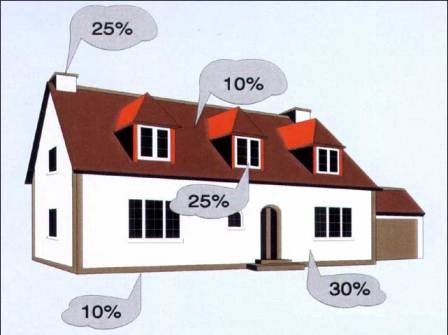
Note! This safety factor takes into account the possibility of a pressure drop in the gas pipeline system in winter, in addition to unforeseen heat losses. For example, as the photo shows, due to a broken window, poor thermal insulation of doors, severe frosts. Such a margin allows you to widely regulate the temperature regime.
It should be noted that when the amount of thermal energy is calculated, its losses throughout the building are not evenly distributed, on average, the figures are as follows:
- external walls lose about 40% of the total figure;
- 20% goes through the windows;
- floors give about 10%;
- 10% escapes through the roof;
- 20% leave through ventilation and doors.
Material coefficients
Further, the methodology for calculating thermal energy for heating takes into account the materials of the house. They directly affect the level of heat loss. When calculating, in order to take into account all factors, the following coefficients are applied:
- K1 - type of windows;
- K2 - thermal insulation of walls;
- K3 - means the ratio of the area of \u200b\u200bwindows and floors;
- K4 - the minimum temperature regime outside;
- K5 - the number of external walls of the building;
- K6 - number of storeys of the structure;
- K7 - the height of the room.
As for windows, their heat loss coefficients are:
- traditional glazing - 1.27;
- double-glazed windows - 1;
- three-chamber analogues - 0.85.
The larger the windows are relative to the floors, the more heat the building loses.
| The ratio of window and floor areas | Coefficient |
| 10% | 0.8 |
| 10/19% | 0,9 |
| 20% | 1 |
| 21/29% | 1.1 |
| 30% | 1.2 |
| 31/39% | 1.3 |
| 40% | 1.4 |
| 50% | 1,5 |
When calculating the consumption of thermal energy for heating, keep in mind that the material of the walls has the following coefficient values:
- concrete blocks or panels - 1.25 / 1.5;
- timber or logs - 1.25;
- masonry in 1.5 bricks - 1.5;
- masonry in 2.5 bricks - 1.1;
- foam concrete blocks - 1.
At negative temperatures, heat leakage also increases.
- Up to -10°, the coefficient will be equal to 0.7.
- From -10° it will be 0.8.
- At -15 °, you need to operate with a figure of 0.9.
- Up to -20° - 1.
- From -25° the value of the coefficient will be 1.1.
- At -30° it will be 1.2.
- Up to -35°, this value is 1.3.
When you calculate thermal energy, keep in mind that its loss also depends on how many external walls are in the building:
- one external wall - 1%;
- 2 walls - 1.2;
- 3 outer walls - 1.22;
- 4 walls - 1.33.
The number of floors or the type of premises located above the living room affect the coefficient K6. When the house has two floors or more, the calculation of heat energy for heating takes into account the coefficient 0.82. If at the same time the building has a warm attic, the figure changes to 0.91, if this room is not insulated, then to 1.
The height of the walls affects the level of the coefficient as follows:
- 2.5 m - 1;
- 3 m - 1.05;
- 3.5 m - 1.1;
- 4 m - 1.15;
- 4.5 m - 1.2.
Among other things, the method for calculating the need for thermal energy for heating takes into account the area of \u200b\u200bthe room - Pk, as well as the specific value of heat losses - UDtp.
The final formula for the necessary calculation of the heat loss coefficient looks like this:
Tp \u003d UDtp ∙ Pl ∙ K1 ∙ K2 ∙ K3 ∙ K4 ∙ K5 ∙ K6 ∙ K7. In this case, UDtp is 100 W/m².
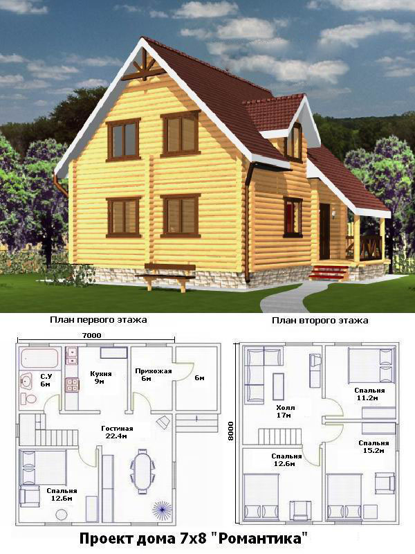
Calculation example
The building for which we will find the load on the heating system will have the following parameters.
- Windows with double glazing, i.e. K1 is 1.
- External walls - foam concrete, the coefficient is the same. 3 of them are external, in other words K5 is 1.22.
- The square of the windows is 23% of the same indicator of the floor - K3 is 1.1.
- Outside temperature is -15°, K4 is 0.9.
- The attic of the building is not insulated, in other words, K6 will be 1.
- The height of the ceilings is three meters, i.е. K7 is 1.05.
- The area of the premises is 135 m².
Knowing all the numbers, we substitute them into the formula:
Fri = 135 ∙ 100 ∙ 1 ∙ 1 ∙ 1.1 ∙ 0.9 ∙ 1.22 ∙ 1 ∙ 1.05 = 17120.565 W (17.1206 kW).
Now you can calculate the power of the heat generator with your own hands:
Mk = 1.2 ∙ 17.1206 = 20.54472 kW.
Hydraulic calculation for heating system
This design stage will help you choose the right length and diameter of pipes, as well as correctly balance the heating system using radiator valves. This calculation will give you the opportunity to choose the power of the electric circulation pump.
According to the results of hydraulic calculations, you need to find out the following numbers:
- M is the amount of water flow in the system (kg/s);
- DP - head loss;
- DP1, DP2… DPn, is the pressure loss, from the heat generator to each battery.
We find out the consumption by the formula:
M = Q/Cp ∙ DPt
- Q means the total heating power, taken taking into account the heat losses of the house.
- Cp is the specific heat capacity of water. To simplify the calculations, it can be taken as 4.19 kJ.
- DPt is the temperature difference at the inlet and outlet of the boiler.
In the same way, it is possible to calculate the consumption of water (coolant) in any section of the pipeline. Select sections so that the fluid velocity is the same. According to the standard, division into sections must be carried out before reduction or tee. Next, sum up the power of all batteries to which water is supplied through each pipe interval. Then substitute the value in the above formula. These calculations must be made for the pipes in front of each of the batteries.
V = M/P F
- V is the speed of advancement of the coolant (m/s);
- M - water consumption in the pipe section (kg / s);
- P is its density (1 t/m³);
- F is the cross-sectional area of the pipes (m²), it is found by the formula: π ∙ r / 2, where the letter r means the inner diameter.
DPptr = R ∙ L,
- R means specific friction loss in the pipe (Pa/m);
- L is the length of the section (m);
After that, calculate the pressure loss on the resistances (fittings, fittings), the action formula:
Dms = Σξ ∙ V²/2 ∙ P
- Σξ denotes the sum of the coefficients of local resistance in a given section;
- V is the speed of water in the system
- P is the density of the coolant.
Note! In order for the circulation pump to sufficiently provide heat to all batteries, the pressure loss on the long branches of the system should not be more than 20,000 Pa. The coolant flow rate should be from 0.25 to 1.5 m/s.
If the speed is above the specified value, noise will appear in the system. The minimum speed value of 0.25 m / s is recommended by snip No. 2.04.05-91 so that the pipes do not air.
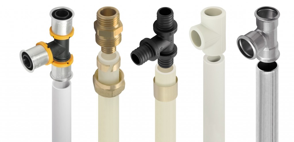
In order to comply with all the voiced conditions, it is necessary to choose the right diameter of the pipes. You can do this according to the table below, which shows the total power of the batteries.
| Pipe material and diameter | Power minimum (kW) | Maximum power (kW) |
| Metal-plastic, 16 mm | 2.8 | 4.5 |
| Metal-plastic, 20 mm | 5 | 8 |
| Metal-plastic, 26 mm | 8 | 13 |
| Metal-plastic, 32 mm | 13 | 21 |
| Polypropylene, 20 mm | 4 | 7 |
| Polypropylene, 25 mm | 6 | 11 |
| Polypropylene, 32 mm | 10 | 18 |
| Polypropylene, 40 mm | 16 | 28 |
At the end of the article, you can watch a tutorial video on its topic.
Consumption of thermal energy for heating
The heating system of your home must be assembled correctly. This is the only way to guarantee its efficient functioning, fuel economy, high heat transfer and noiseless operation. All four qualities determine the degree of comfortable living inside the house in winter. Therefore, heat calculation is a necessary procedure.
To correctly calculate, you need knowledge of the formulas and various coefficients, which are based on the condition of the house as a whole.
What is needed for the calculation?
The so-called thermal calculation is carried out in several stages:
- First you need to determine the heat loss of the building itself. Typically, heat losses are calculated for rooms that have at least one external wall. This indicator will help determine the power of the heating boiler and radiators.
- Then the temperature regime is determined. Here it is necessary to take into account the relationship of three positions, or rather, three temperatures - the boiler, radiators and indoor air. The best option in the same sequence is 75C-65C-20C. It is the basis of the European standard EN 442.
- Taking into account the heat loss of the room, the power of the heating batteries is determined.
- The next step is hydraulic calculation. It is he who will allow you to accurately determine all the metric characteristics of the elements of the heating system - the diameter of pipes, fittings, valves, and so on. Plus, based on the calculation, an expansion tank and a circulation pump will be selected.
- The power of the heating boiler is calculated.
- And the last stage is the determination of the total volume of the heating system. That is, how much coolant is needed to fill it. By the way, the volume of the expansion tank will also be determined based on this indicator. We add that the volume of heating will help you find out if the volume (number of liters) is enough expansion tank, which is built into the heating boiler, or you will have to purchase additional capacity.
By the way, about heat losses. There are certain norms that are set by experts as a standard. This indicator, or rather, the ratio, determines the future efficient operation of the entire heating system as a whole. This ratio is - 50/150 W/m². That is, the ratio of the power of the system and the heated area of \u200b\u200bthe room is used here.
Thermal calculation
Thermal energy consumption standards
Thermal loads are calculated taking into account the power of the heating unit and the heat losses of the building. Therefore, in order to determine the capacity of the designed boiler, it is necessary to multiply the heat loss of the building by a multiplying factor of 1.2. This is a kind of margin equal to 20%.
Why is this ratio needed? With it, you can:
- Predict the drop in gas pressure in the pipeline. After all, in winter there are more consumers, and everyone tries to take more fuel than the rest.
- Vary the temperature inside the house.
We add that heat losses cannot be distributed evenly throughout the building structure. The difference in indicators can be quite large. Here are some examples:
- Up to 40% of the heat leaves the building through the outer walls.
- Through floors - up to 10%.
- The same applies to the roof.
- Through the ventilation system - up to 20%.
- Through doors and windows - 10%.
materials
So, we figured out the design of the building and made one very important conclusion that heat losses that need to be compensated depend on the architecture of the house itself and its location. But much is also determined by the materials of the walls, roof and floor, as well as the presence or absence of thermal insulation. This is an important factor.
For example, let's determine the coefficients that reduce heat loss, depending on window structures:
- Ordinary wooden windows with ordinary glass. To calculate the thermal energy in this case, a coefficient equal to 1.27 is used. That is, through this type of glazing, thermal energy leaks, equal to 27% of the total.
- If plastic windows with double-glazed windows are installed, then a coefficient of 1.0 is used.
- If plastic windows are installed from a six-chamber profile and with a three-chamber double-glazed window, then a coefficient of 0.85 is taken.
We go further, dealing with the windows. There is a certain relationship between the area of \u200b\u200bthe room and the area of \u200b\u200bwindow glazing. The larger the second position, the higher the heat loss of the building. And here there is a certain ratio:
- If the window area in relation to the floor area has only a 10% indicator, then a coefficient of 0.8 is used for the calculation.
- If the ratio is in the range of 10-19%, then a coefficient of 0.9 is applied.
- At 20% - 1.0.
- At 30% -2.
- At 40% - 1.4.
- At 50% - 1.5.
And that's just the windows. And there is also the influence of the materials that were used in the construction of the house on thermal loads. Let's arrange them in a table where wall materials will be located with a decrease in heat losses, which means that their coefficient will also decrease:
As you can see, the difference from the materials used is significant. Therefore, even at the stage of designing a house, it is necessary to determine exactly what material it will be built from. Of course, many developers build a house based on the budget allocated for construction. But with such layouts, it is worth reconsidering it. Experts assure that it is better to invest initially in order to later reap the benefits of savings from the operation of the house. Moreover, the heating system in winter is one of the main items of expenditure.
Room sizes and building heights
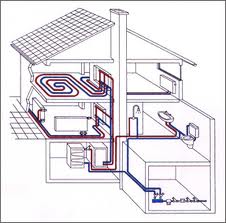
Heating system diagram
So, we continue to understand the coefficients that affect the formula for calculating heat. How does room size affect heat loads?
- If the ceiling height in your house does not exceed 2.5 meters, then a factor of 1.0 is taken into account in the calculation.
- At a height of 3 m, 1.05 is already taken. A slight difference, but it significantly affects heat loss if the total area of \u200b\u200bthe house is large enough.
- At 3.5 m - 1.1.
- At 4.5 m -2.
But such an indicator as the number of storeys of a building affects the heat loss of a room in different ways. Here it is necessary to take into account not only the number of floors, but also the location of the room, that is, on which floor it is located. For example, if this is a room on the ground floor, and the house itself has three or four floors, then a coefficient of 0.82 is used for the calculation.
When moving the room to the upper floors, the rate of heat loss also increases. In addition, you will have to take into account the attic - is it insulated or not.
As you can see, in order to accurately calculate the heat loss of a building, it is necessary to determine various factors. And all of them must be taken into account. By the way, we have not considered all the factors that reduce or increase heat losses. But the calculation formula itself will mainly depend on the area of \u200b\u200bthe heated house and on the indicator, which is called the specific value of heat losses. By the way, in this formula it is standard and equal to 100 W / m². All other components of the formula are coefficients.
Hydraulic calculation
So, we have decided on heat losses, the power of the heating unit has been selected, it remains only to determine the volume of the required coolant, and, accordingly, the dimensions, as well as the materials of the pipes, radiators and valves used.
First of all, we determine the volume of water inside the heating system. This will require three indicators:
- The total power of the heating system.
- Temperature difference at the outlet and inlet to the heating boiler.
- Heat capacity of water. This indicator is standard and equal to 4.19 kJ.
Hydraulic calculation of the heating system
The formula is as follows - the first indicator is divided by the last two. By the way, this type of calculation can be used for any part of the heating system. Here it is important to break the line into parts so that in each the speed of the coolant is the same. Therefore, experts recommend making a breakdown from one shut-off valve to another, from one heating radiator to another.
Now we turn to the calculation of the pressure loss of the coolant, which depends on the friction inside the pipe system. For this, only two quantities are used, which are multiplied together in the formula. These are the length of the main section and specific friction losses.
But the pressure loss in shutoff valves calculated using a completely different formula. It takes into account indicators such as:
- Heat carrier density.
- His speed in the system.
- The total indicator of all coefficients that are present in this element.
In order for all three indicators, which are derived by formulas, to approach standard values, it is necessary to choose the right pipe diameters. For comparison, we will give an example of several types of pipes, so that it is clear how their diameter affects heat transfer.
- Metal-plastic pipe with a diameter of 16 mm. Her thermal power varies in the range of 2.8-4.5 kW. The difference in the indicator depends on the temperature of the coolant. But keep in mind that this is a range where the minimum and maximum values are set.
- The same pipe with a diameter of 32 mm. In this case, the power varies between 13-21 kW.
- Polypropylene pipe. Diameter 20 mm - power range 4-7 kW.
- The same pipe with a diameter of 32 mm - 10-18 kW.
And the last is the definition of a circulation pump. In order for the coolant to be evenly distributed throughout the heating system, it is necessary that its speed be not less than 0.25 m / s and not more than 1.5 m / s. In this case, the pressure should not be higher than 20 MPa. If the coolant velocity is higher than the maximum proposed value, then the pipe system will work with noise. If the speed is less, then airing of the circuit may occur.
Conclusion on the topic
For ordinary consumers, non-specialists who do not understand the nuances and features of heat engineering calculations, everything that has been described above is a difficult topic and somewhere even incomprehensible. And it really is. After all, it is quite difficult to understand all the intricacies of the selection of a particular coefficient. That is why the calculation of thermal energy, or rather, the calculation of its amount, if such a need arises, is best entrusted to a heating engineer. But it is impossible not to make such a calculation. You yourself could see for yourself that a fairly wide range of indicators depend on it, which affect the correct installation of the heating system.