
How a piezometric graph of a heat network is built. Construction of a piezometric graph, mechanical calculation of pipelines - heat supply of a city district
When designing and operating branched heat networks, a piezometric graph is widely used, on which the terrain and the height of the attached buildings, the pressure in the network at any point in the network and subscriber systems are plotted. Figure 10 shows a piezometric graph of a two-pipe water heating system.
The construction of a piezometric graph is carried out as follows (Fig. 10).

Rice. 10. Piezometric graph of a two-pipe water heating network (a) and schemes for connecting heating installations to a heating network (b):
I - dependent with an elevator; II - dependent with an elevator and a pressure regulator on the return line; III - dependent with a mixing pump (pump on the jumper); IV - independent; 1 - air valve; 2 - expander; 3- heating device; 4-RDDS - pressure regulator "to yourself"; 5 - water-water heater; 6 - pump; 7 - elevator
1. A coordinate system is built, where the length of the main section is plotted along the OX axis, and the pressure drop (100 .. .120 m) is plotted along the OY axis.
2. The axis of network pumps is taken as the origin of coordinates. Apply a profile of the area along the highway.
3. The profile is applied to the scale of the height of the attached buildings.
4. Draw a static head line 5 m above the tallest building (line S–S).
5. Preliminarily, the pressure on the suction side of the network pumps is assumed to be 10–15 m and a horizontal line A–0 is applied.
6. From t.A, the lengths of the calculated sections are plotted along the abscissa axis with a cumulative total, and along the ordinate axis, the head loss according to the data hydraulic calculation (ΔN).
7. The resulting A-B line is a piezometric return line.
8. From t. B upwards, pressure losses on the elevator in the subscriber units of the last consumer are postponed: ΔН e=15m, according to SNiP Thermal networks; receive v. B 1 . If the connection is made without an elevator, that is, the water temperature in the supply line is 95 ° C, then 4 m is set aside to obtain t. 1–2 m w.c. or 10–20 kPa);
9. Build a piezometric line of the falling line, which is a mirror image of the piezometric line of the return line. Get the line A 1 -B 1.
10. From point A 1, pressure losses are laid upwards in the boiler CHP or boiler room, NB= 10–20 m.
11. Branches are applied on the terrain profile. The connection of consumers located on branches to heating networks is shown at the point of connection to the main.
12. The piezometric graph constructed in this way makes it easy to set the pressure at any point in the supply and return pipelines.
The pressure at any point of the pipelines of the heating network is determined by the length of the segment between this point and the pressure line (in the supply or return pipeline).
The available pressure at each point is equal to the pressure difference in
forward and return lines.
It should be noted that with direct connection of local systems, the return pipeline of the heating network is hydraulically connected to the local system. Therefore, the pressure in the return pipeline is completely transferred to the local system and vice versa.
During the initial construction of the piezometric graph, the pressure on the suction side of the network pumps was taken arbitrarily.
Moving the piezometric graph parallel to itself allows you to take any pressure on the suction side of the network pumps and, accordingly, in local systems.
When choosing the position of the piezometric graph, consider the following:
1. The maximum pressure in the supply pipelines is limited by the strength of the water heating installations. The maximum allowable pressure for steel hot water boilers is 250 m, cast iron - 60 m, heaters -100 m, heaters - 80 m.
2. The pressure at any point of the return line must not be higher than the permissible operating pressure in local systems: 60 m.
When determining the scheme for connecting consumers to heating networks, check:
1. The supply line must be higher than the building and not more than 60–100 m and not lower than 10–40 m according to the non-boiling condition.
2. The return line should be 5–10 m higher than the building and no more than 60 m.
3. The static head was less than 60 m.
4. The available head was greater than or equal to 1.5 m to connect the elevator.
If these conditions are met, then the consumer can be connected according to a dependent direct scheme to the heating network using an elevator.
If condition 1 is not met, then an independent connection scheme is used, through a heat exchanger.
If condition 2 is not met:
– hydrodynamic piezometric head in the return line is less than the height of the building – it is necessary to install a pressure regulator “to yourself”;
- pressure in the return line is more than 60 m - an independent connection scheme is used.
If condition 3 is not met, that is, the static head is more than 60 m, an independent connection scheme is used.
If condition 4 is not met, that is, the available head in the network is less than 15 m to use the elevator, you can use a dependent connection scheme with a pump on the jumper.
3. The pressure in the return pipeline must ensure the filling of the upper devices of the heating systems, that is, the pressure line in the return pipeline must be higher than the buildings.
4. The pressure in the return line must not be lower than 5–10 mm of water column to avoid the formation of a vacuum.
5. The pressure on the suction side of the network pump must not be lower than the 5 m wc line.
6. From the condition of non-boiling of water at its design temperature, the minimum allowable piezometric head in the supply line of the heating network should be 40 m for 150 0 C, 130 0 C -20 m, 120 0 C -10 m.
7. The available pressure at the end point of the network must be equal to or greater than the calculated pressure loss, and at the subscriber input at the calculated coolant flow.
8. Static pressure should not exceed 60 m w.c. from the strength condition cast iron radiators. Reduction of static pressure in thermal circuits can be carried out by automatically disconnecting the network from tall buildings.
9. Piezometric pressures at the subscriber inputs, that is, in the supply line, must exceed the height of the subscriber hot water supply installations.
After constructing a piezometric graph, it is necessary to determine:
1. pressure loss of network pumps;
2. a way to connect consumers to heating networks.
The main task of hydraulic calculation is the optimal choice of pipeline diameters and determination of pressure losses in heat networks. In accordance with the master plan and the initial data, a design scheme heating networks, for the end points of which the centers of quarters (neighborhoods) and the industrial hub are conventionally taken. At the stage of course design, it is possible not to take into account the need for sectional valves on main pipelines (every 1-3 km) and blocking jumpers between highways (every 1-3 km).
On the design diagram, drawn on a scale, for each section, the length, the estimated coolant flow rate and the diameter of the pipelines are indicated (Fig. 3.1).
The flow rate of steam supplied to industrial and technological consumers P is set, and the estimated flow rates of network water (kg / s) are calculated by the formulas:
For heating
For ventilation
For hot water supply in STZ
Total
where  ,
, - temperature of direct network water and water after the DHW heater at the break point of the temperature graph,
c - specific heat capacity of water, equal to 4.19 kJ / (kg ° С)
k z - coefficient taking into account the share of the average water consumption for hot water supply when regulating the mixed load according to the heating load.
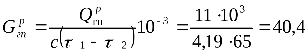
Estimated costs of network water for industrial. company
For heating and ventilation
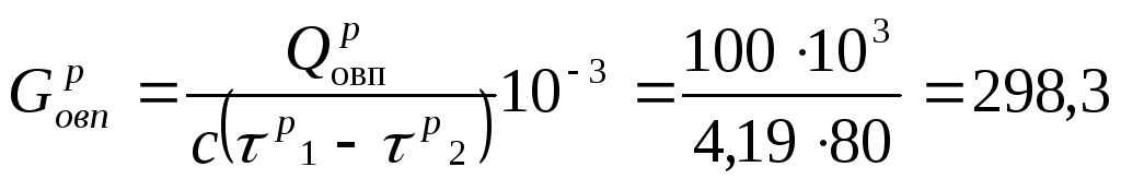 kg/s
kg/s
For hot water supply
 kg/s
kg/s
Total
Estimated consumption of network water in the non-heating period
G g max - maximum water consumption for domestic hot water supply
G  = 2.4G
  = 2.4 414.2 = 994.08 kg/s = 3578.7 t/h
It is convenient to perform hydraulic calculation using special tables or nomograms. The share of pressure losses in local resistances is α m =0,25-0,35.
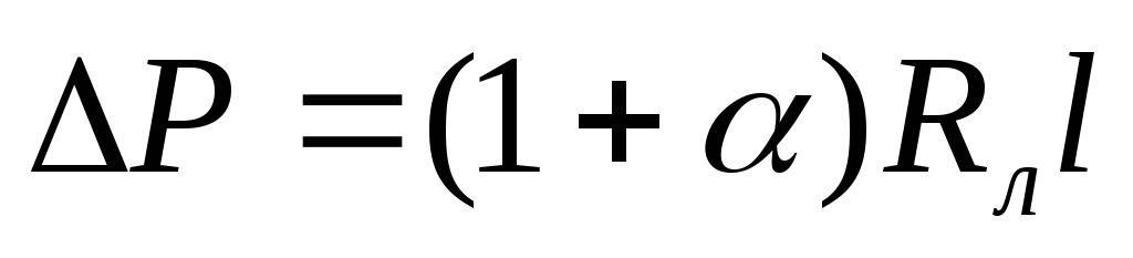
It is advisable to carry out the calculation in tabular form separately for the settlement main (from the source to the most remote consumer) and branches. Specific pressure losses R l in water heating networks are determined on the basis of technical and economic calculations. It is allowed to choose the diameters of pipelines of water heating networks at R l  80 Pa / m in the design line and R l 300 Pa/m in branches. In steam networks, the steam speed must be below the permissible values: superheated steam - 50 m/s at Dу 200 mm and 80 m/s at Dy > 200 mm, saturated steam - respectively 35 and 60 m/s.
Based on the results of the hydraulic calculation, a piezometric graph of the water heating network and the condensate pipeline is built. The piezometric graph is built for the heating and non-heating periods.
Maximum consumption of network water in the non-heating period
 kg/s = 5187.6 t/h
Table 3.10. Hydraulic calculation
|
Water consumption (steam) |
Section length |
Diameter (inner/outer) |
Specific pressure drop |
Water speed (steam), |
Pressure loss
|
head loss, ΔH, m.w.st.*. |
|
|
Settlement highway |
|||||||
|
Branches |
|||||||
 , Pa
, Pa* - 1 m.v.st. \u003d 9.81 10 3 Pa
To build a piezometric graph, we will take the scales: vertical Mv 1:1000 and horizontal Mg 1:10000. Let's build, using the horizontal lines and the lengths of the sections, the longitudinal profiles of the main highway and branches.
When constructing a piezometric graph, the possibility of using rational schemes for connecting consumers to heating networks is taken into account. The static pressure should not exceed the allowable strength of the equipment of heat-consuming systems, but by 0.05 MPa it should be more than the height of the consumer with the highest geodetic mark. Otherwise, independent schemes for connecting consumers and dividing heating networks into independent zones are provided.
Having previously assumed the pressure on the suction side of the network pumps Hvs = 30 meters, we build a line of pressure losses in the return line of the heating network AB. The excess of point B in relation to point A will be equal to the pressure loss in the return line, which is assumed to be 15.4 meters. Next, we build the line BC - the line of available pressure for the heat supply system of quarter No. 7. The available pressure is assumed to be 35 meters. Then we build the pressure loss line of the supply line of the heating network CD. The excess of point D in relation to point C is equal to the pressure loss in the supply line and is 15.4 meters.
Next, we build the line DE - the line of pressure losses in the heating equipment of the heat source, which are taken equal to 25 meters. The position of the line of static pressure S-S is chosen from the condition of preventing "exposure", "crushing" and boiling of the coolant. Next, we proceed to the construction of a piezometric graph for not heating period.
Pressure loss in the supply and return pipelines at the total consumption of network water  , different from the calculated one, are recalculated in proportion to the square of network water consumption, i.e.
The pressure losses in the heat source equipment, as well as the available pressure for the quarterly heating network, will be taken similar to those for the heating period. Using the technique applied earlier, we will build a piezometric graph for the non-heating period (A B'C'D'E'). After building piezometric graphs, you should make sure that the location of their lines meets the requirements for developing hydraulic regimes.
According to the piezometric graph, the required pressures of the network and make-up pumps are selected. The head of the network pumps is assumed to be equal to the sum of the head losses in the heat treatment plant of the source, in the supply and return pipelines of the calculated main and heat-consuming systems. The performance of network pumps is selected according to the total estimated water flow in the STZ. The pressure of the make-up pumps is selected according to the static pressure of the system, and the performance - according to the sum of the maximum water intake  and leaks in the STZ (0.75% of the volume of water in the system, equal to 65 m 3 /MW).
For a closed heat supply system, we will select network and make-up pumps.
Required head of the network pump H sn = 76 m
Required supply of the network pump G sn for a closed system, t / h.
G sn= 2205 kg/s= 7938 t/h
According to the application, we accept for installation three working pumps of the D4000-95 type (one standby), providing a total supply of 12000 t / h.
To select a make-up pump, we determine its head H pn, the head of make-up pumps in the STZ is selected according to the static pressure of the system H st = 45 m
Determine pump flow
G mon \u003d G ut + G hmax
The leakage rate at a specific volume of 65 m 3 per 1 MW of the thermal power of the system will be:
G ut = 0.0075 V syst = 0.0075 65 Q = 0.0075 65 713 = 347.6 t/h
The required supply of the make-up pump G mon will be
G mon \u003d G ut + G hmax \u003d 347.6 + 3578.7 \u003d 3926.3 t / h
According to the application, we accept two working and one standby D2500-45 pumps for installation in parallel, providing the required parameters with an efficiency of 85%.
In the types of T and PT turbines proposed for installation at CHPPs, heaters of the PST type with a design water pressure of 0.88 MPa are used.
In conclusion, it is necessary to select the number and volume of central storage tanks (BA) in the STZ. In the SPZ with a thermal power of 100 MW or more, it is planned to install tanks (at least two) for the supply of chemically treated and deaerated make-up water, the capacity of which should be 3% of the volume of water in the ST, i.e. 1.4 thousand m 3. Typically, thermal power plants are equipped with tanks with a capacity of 1; 5 and 10 thousand m 3. This means that we install two tanks for the supply of chemically purified and deaerated make-up water with a capacity of 1000 m 3.
A piezometric graph is developed for two modes. Firstly, for a static mode, when there is no water circulation in the heat supply system. It is assumed that the system is filled with water at a temperature of 100°C, thereby eliminating the need to maintain excess pressure in the heat pipes to avoid boiling of the coolant. Secondly, for the hydrodynamic regime - in the presence of coolant circulation in the system.
The development of the schedule begins with a static mode. Initially, they are looking for the possibility of such an arrangement on the graph of the full static pressure line so that all subscribers can be connected to the heating network according to dependent schema. To do this, the static pressure should not exceed the allowable one from the strength condition of the subscriber installations and should ensure that local systems are filled with water. The presence of a common static zone for the entire heat supply system simplifies its operation and increases its reliability. It is possible to establish a single level of static pressure only with a calm terrain area of the heat supply area.If there is a significant difference in geodetic elevations of the earth, the establishment of a common
static zone is impossible for the following reasons. The lowest position of the static pressure level is determined from the conditions of filling local systems with water and providing at the highest points of the systems of the tallest buildings located in the zone of the largest geodetic marks, an overpressure of at least 0.05 MPa. Such pressure turns out to be unacceptably high for buildings located in that part of the area that has the lowest geodetic marks. Under such conditions, it becomes necessary to divide the heat supply system into two static zones. One zone for a part of the heat-supply area with low geodetic marks, the other - with high ones.
On fig. 8 9 shows a piezometric graph and circuit diagram heat supply systems for an area with a significant difference in geodetic elevations of the ground level (40 m). The part of the area adjacent to the source of heat supply has zero geodetic marks, in the peripheral part of the area the marks are 40 m. The height of the buildings is 30 and 45 m. systems with an excess head of 5 m, the level of the total static head should be located at around 75 m (line S2-S2). In this case, the static head will be equal to 35 m. However, a head of 75 m is not allowed for buildings I and II located at the zero mark. For them, the permissible highest position of the level of the full static
Lators RDDS (10) and RD2 (9), DYA 0 pґ, - pressure actuated on the RDDS regulator valve
In hydrodynamic mode, I-IV - subscribers, / - make-up water tank, 2, 3 - make-up pump and make-up regulator of the lower zone, 4 - upstream pump, 5 - cogeneration steam-water heaters, 6 - network pump, 7 - peak water heater, 8 , 9 - make-up pump and make-up regulator of the upper zone, 10 - pressure regulator "to yourself" RDDS 11 - pressure check valve corresponds to 60 m. Thus, under the conditions under consideration, it is impossible to establish a common static zone for the entire heat supply system.
A possible solution is to divide the heat supply system into two zones with different levels of total static pressure - the lower one with a level of 50 m (line 5] -Si) and the upper one with a level of 75 m (line S2-S2). With this solution, all consumers can be connected to the heat supply system according to a dependent scheme, since the static pressures in the lower and upper zones are within acceptable limits. .
So that when the circulation of water in the system stops, the levels of static pressures are established in accordance with the accepted two values, a separating device is located at the place of their connection (see Fig. 8.9, b). This device protects heating network from increased pressure when the circulation pumps stop, automatically cutting it into two hydraulically independent zones: upper and lower.
When the circulation pumps are stopped, the pressure drop in the return pipeline of the upper zone is prevented by the pressure regulator “up to itself” RDDS 10, which maintains a constant predetermined pressure Yardds at the point of impulse selection. When the pressure drops, it closes. A pressure drop in the supply line is prevented by a non-return valve 11 installed on it, which also closes. Thus, RDDS and a check valve cut the heating system into two zones. To recharge the upper zone, a recharge pump 8 is installed, which takes water from the "lower zone and supplies the upper one, and a recharge controller 9. The pressure developed by the pump is equal to the difference between the hydrostatic heads of the upper and lower zones. The recharge of the lower zone is carried out by the recharge pump 2 and the recharge controller 3.
The RDDS regulator is set to the pressure Yardds (see Fig. 8.9, a). At the same pressure, the feed regulator RD2 is set.
In hydrodynamic mode, the RDDS regulator maintains the pressure at the same level. At the beginning of the network, a make-up pump with a regulator maintains the Hoi pressure. The difference between these pressures is spent on overcoming hydraulic resistance in the return pipeline between the separating device and the circulation pump of the heat source, the rest of the pressure is released in the throttle substation at the RDDS valve. On fig. 8.9, and this part of the pressure is shown by the value of ARdds. The throttle substation in hydrodynamic mode allows maintaining the pressure in the return line of the upper zone not lower than the accepted level of static pressure S2 - S2.
Piezometric lines corresponding to the hydrodynamic regime are shown in Figs. 8.9, a. The highest pressure in the return pipeline at consumer IV is 90-40 = 50 m, which is acceptable. The time in the return line of the lower zone is also within acceptable limits.
In the supply pipeline, the maximum head after the heat source is 160 m, which does not exceed the allowable pressure from the pipe strength * condition. The minimum piezometric head in the supply pipeline is 110 m, which ensures non-boiling of the high-temperature coolant, since at a design temperature of 150 ° C, the minimum allowable pressure is 40 m.
Thus, the piezometric graph developed for static and hydrodynamic modes provides the possibility of connecting all subscribers according to a dependent scheme.
Another possible solution for the hydrostatic mode of the heat supply system shown in fig. 8.9, is the connection of a part of subscribers according to an independent scheme. There may be two options here. The first option is to install general level static pressure on
mark 50 m (line Si - Si), and the buildings located on the upper geodetic marks, connect according to an independent scheme. In this case, the static head in the water-to-water heating heaters of buildings in the upper zone on the side of the heating coolant will be 50-40 = = 10 m, and on the side of the heated coolant it will be determined by the height of the buildings. The second option is to set the total level of static pressure at around 75 m (line S2 - Ss) with the buildings of the upper zone connected according to a dependent scheme, and the buildings of the lower zone - according to an independent one. In this case, the static head in water-to-water heaters on the side of the heating coolant will be equal to 75 m, i.e., less than the permissible value (100 m).
With a calm terrain, but a large length of heating networks, it becomes necessary to install pumping substations on the supply and return lines. This is due to the fact that the allowable pressure losses in the supply and return pipelines are insufficient to ensure optimal hydraulic slopes, and their increase by installing circulation pumps that develop high pressures is impossible from the condition of pipeline strength and. When booster substations are installed along the route of the heating network, the total pressure of the pumps increases, which ensures the circulation of water in the system, the hydraulic slopes increase with the position of the upper and lower pressure limits in the supply and return pipelines unchanged. The installation of booster substations also makes it possible to increase throughput operating heating system.
|
|

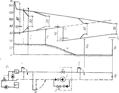
On fig. 8.10 at the top is a piezometric graph of a long-distance heating network, and at the bottom is the location of the heat source, pipelines and pumping stations. If, while maintaining the load of the heating network and the slopes of the piezometric lines, it is limited only to the installation of circulation pumps at the station, then they should develop a head of 140 + 40 + 40 = 220 m. The maximum piezometric head at the beginning of the network will be 210 m, which is unacceptable from the condition of pipeline strength. Such a piezometric plot is shown in Fig. 8.10 dotted line. The pressure in the return line at the end of the line is 100 m, which does not allow consumers to be connected according to a dependent scheme. This pressure is the limit for independent
Rice. 8.10. Piezometric gra. fictitious heating network of great length
1 - heat source;
2 - the location of booster pumps on the supply and return heat pipelines; 3 - end subscriber; S - S - line of full static head; #„, N N,
N p. and n. P
The pressures developed by the pumps: network, make-up, pumping up on the supply line, pumping up on the return line;
I3 - height of buildings
connection. When installing pumping substations, the head of the circulation * pump of the heat source is reduced to 140 m, and the maximum head at the beginning of the network is up to 130 m, i.e., to the permissible one. At the same time, the decrease in pressure in the supply pipeline between the heat source and the pumping substation does not cause an unacceptable decrease in pressure at the end of the network. Booster pumps increase the pressure in this zone from 80 to 120 m. As a result of this solution, the pressure in the supply pipeline varies from 80 to 130 m.
The substation on the return line reduces the pressure at the end of the network between the substation and subscriber 3. In this zone, the pressure in the return line does not exceed the allowable value of 60 m.
Thus, as a result of the installation of booster pumping substations on a long heating network, it is possible to maintain the location of piezometric lines both in the supply and return pipelines within acceptable limits while maintaining an economically justified specific pressure drop.
In the case of a decrease in the terrain from the heat source, the pressure in the return line of the peripheral zone of the area increases significantly and it may go beyond the permissible limits. To reduce the pressure in this part of the return line, a booster pumping substation is installed on it. Such a case is shown in Fig. 8.11. If you do not install a pumping substation on the return line, then the pressure at the end user 3 will be 60 + 30 = 90 m, which will not allow dependent connection. Piezometric lines of supply and return heat pipes for the system b. without a booster substation with a head developed by the circulation pump of 130 + 30 = 160 m are shown in fig. 8.11 dotted line. The maximum pressure in the supply line turns out to be 140 + 30 \u003d 170 m, that is, it exceeds the allowable one (160 m). As a result of the installation of booster pumps on the return heat pipeline, the piezometric line of the heat supply pipeline drops equidistantly by 30 m, and the pressure in the return heat pipeline between the pumping substation and the end user is in the zone
|
Rice. 8 12. Piezometric graph of the heat network with a significantly decreasing terrain from the heat source and dividing the system into two static zones l - piezometric graph, b - basic diagram of the heat supply system; /-IV - subscribers; Si - Si - line of total static pressure in the upper zone; S2 - Sj - line of total static pressure in the lower zone; 1 - cutting machine; 2 - booster pump; 3 - lower zone feed regulator |
Pouring the system into two static zones: the upper one near the source and the lower one on the deripherium. Such a case is shown in Fig. 8.12. To reduce the pressure in the return line, a pumping substation was installed at the end of the line at point M. The pumps develop a head of 40 m. This reduces the head developed by the network pumps to 85 m and, accordingly, reduces the pressure in the supply line.
The heating network is divided into two static zones: the upper one near the heat source with a piezometric head of 50 m and the lower one in the peripheral part of the network with a piezometric head of 50 m. on the return line - check valve. When the pumps stop, the pressure in the pipelines begins to equalize and the pressure in the return pipeline increases in the section from the pumping substation to the end point IV. The increase in pressure is transmitted through the impulse tube to the regulator that controls the splitting valve, the valve closes and hydraulically separates the supply line into two zones. The flow of water from the upper zone to the lower one is prevented by a check valve installed on the return line. As a result, in static mode, the network will be divided into two zones with levels Si - Si and S2 - 52.
Maintaining the static level of the upper zone is provided by the feeding device of the heat source. The static level of the lower zone is maintained by a two-pulse throttle valve 3. The main impulse is the pressure in the return line, the resolving impulse is the pressure in the supply line of the lower zone.
To analyze the operation of heat networks, select network equipment, schemes for connecting subscribers to heat networks, it is necessary to develop hydraulic modes of water heating networks (piezometric graphs). They show the change in pressure along the length of pipelines and in elements of heating networks. Hydraulic modes should be developed for heating and non-heating periods, as well as for emergency modes.
A piezometric graph is built for two operating modes: static, when the network pump is not working, and dynamic, when the network pump is running. In static mode, there is no water circulation, and its pressure is the same at all points of the pipelines. The value of this pressure must be sufficient to fill the local heating, ventilation and hot water systems in the event of a shutdown of the mains pump. In practice, the static pressure is maintained by the operation of a make-up pump connected to the suction pipe of the mains pump. Accordingly, the pressure developed by the make-up pump must be equal to the pressure before the network pump.
When calculating the piezometric graph, the following conditions must be observed:
1. Static pressure in heat supply systems with water as the heat carrier must not exceed the allowable pressure in the heat source equipment, in the pipelines of water heat networks, in the equipment of heat points and in the heating, ventilation and hot water supply systems of consumers directly connected to heat networks.
2. Static pressure should ensure that heating, ventilation and hot water supply systems of consumers directly connected to heating networks are filled with water in the event of a network pump shutdown.
3. The water pressure in the supply pipelines of water heating networks during the operation of network pumps should be taken based on the conditions of non-boiling water at its maximum temperature at any point in the supply pipeline, in the equipment of the heat source and in the devices of consumer systems directly connected to heating networks.
4. The water pressure in the return pipelines of water heating networks during the operation of network pumps must be excessive (at least 0.05 MPa), not exceed the permissible pressure in consumer systems and ensure the filling of local systems (exceed the pressure created by the water column in the heating systems of multi-storey buildings ).
5. The pressure and temperature of the water in the suction pipes of the network, make-up, booster and mixing pumps must not exceed the strength limits of the pump structures.
6. The pressure drop at the input of two-pipe water heating networks to buildings when determining the pressure of network pumps (with elevator connection of heating systems) should be taken equal to the calculated pressure loss at the input and in the local system with a coefficient of 1.5, but not less than 0.15 MPa.
The piezometric graph shows that:
1. The pressure in the suction pipe of the network pump is higher than 5m to avoid covitation.
N Sun. = 10m > 5m
2. The pressure line in the return line is located above all buildings, which ensures that all subscriber heating systems are filled with water. The condition is met.
3. The pressure of the return line does not exceed the permissible strength
N add. = 60 m;
N arr. = 45.8m;
N arr.< Н доп.
The condition is met.
4. The pressure in the supply line H G does not exceed the allowable pressure in terms of the strength of the pipes.
N add. tr. = 100 m;
N under tr. . = 66.7 m;
N under tr. .< Н доп. тр.
The condition is met.
5. The pressure in the return line in static and dynamic modes does not exceed the strength of the allowable pressure in the elements of heat consumption systems:
N arr. = 45.8 m;
N add. = 60 m;
N arr.< Н доп.
The condition is met.
6. The pressure in the supply line exceeds the saturation pressure, i.e. the non-boiling condition for a given coolant temperature of 150°C is observed.
Pump selection
To select any pump, it is necessary to know its performance (delivery) and developed pressure (pressure). In this case, it should be taken into account that the required operating modes (capacity and pressure) must be within the working area of its characteristics. According to the required flow and pressure on the summary graph of the fields, a pump of the required size is preliminarily selected, and then, according to the graphical characteristic, the correct choice is clarified and all other indicators are determined (efficiency, power on the motor shaft, speed, impeller diameter).
The performance of the network pump is equal to the total flow of the coolant in the heating network for heating, ventilation and hot water supply.
The pressure of the network pump, MPa is spent to overcome the resistance of the heat supply system
where - pressure loss in the network equipment of the boiler room, MPa;
Pressure loss in the supply line, MPa;
Pressure loss in the return line, MPa;
Pressure loss at the subscriber, MPa.
The pressure loss is determined from the piezometric graph.
AT two-pipe systems heat supply in the presence of a year-round load of hot water supply, it is advisable to install at least two network pumps with different characteristics: one for operation in cold period with maximum performance, the other - for pumping water in the hot water supply system in the warm season. Performance of the second pump:
![]() .
.
In addition, a backup pump must be installed.
To compensate for water leaks and maintain the required level of piezometric pressure, both in static and dynamic modes, it is necessary to install a make-up pump.
The pressure developed by it is taken equal to the pressure in the suction pipe of the network pump and is determined by the position of the piezometric line in the return line. The flow rate of the make-up pump, m 3 / h, depending on the type of heat supply system, is determined by the formulas:
For feeding a closed heating network
![]() ;
;
For feeding an open heating network
![]() ,
,
where V is the volume of water in the heat supply system, m 3;
Maximum water consumption for hot water supply, m 3 / h.
The volume of water in the heat supply system can be determined by the actual dimensions of the pipes (length and diameter) or by specific indicators that determine the volume of water per unit of thermal power. The volume of water is determined for all elements of the heat supply system: boiler room, external pipelines, local subscriber systems. Specific volumes of water, m 3 / MW can be taken equal to:
For boiler room ![]() ;
;
For outdoor pipelines ![]() ;
;
For heating systems;
For ventilation systems;
For hot water supply systems;
 ,
,  ,
,  ,
, ![]() ;
;
In view of the foregoing, the volume of water can be determined by the formula
where is the total estimated heat consumption in the heat supply system, MW;
, , – settlement costs heat for heating, ventilation and hot water supply, respectively, MW.
The minimum number of operating make-up pumps is assumed to be: in closed systems- one, open - two. In both cases, one standby pump of the same capacity is provided.
In heat supply systems, the following types of pumps can be used as network circulation and make-up pumps:
1. SE - horizontal spiral type with double entry impellers, single-stage. SE type pumps are used as network pumps in large heat supply systems and are installed on the supply pipelines of heating networks for pumping overheated water with a temperature of up to 180 ° C and with an operating pressure at the pump inlet from 0.4 to 2.5 MPa.
2. D - horizontal single-stage with a semi-spiral fluid supply to the impeller. Designed for water with a temperature not exceeding 85°C and a maximum head of 20 m w.c.
3. K - Centrifugal pumps console type.
Characteristics of pumps for heating networks are given in the reference literature.
Calculation of the network pump:
Volume of pumped water for winter conditions:
Volume of pumped water for summer conditions:
![]() , (t/h);
, (t/h);
We select two network pumps:
For winter period two pumps D630-90 with parameters: impeller diameter - 450, nominal flow - 630 m³/h, full head- 63 m, efficiency - 75%, Power on the pump shaft - 365 kW.
For the summer period D200-95 with the following parameters: impeller diameter - 240, nominal flow - 200 m³ / h, total head - 64 m, efficiency - 85%, Pump shaft power - 70 kW.
It also provides for one standby pump D630-90 and one standby pump D200-95.
Feed pump calculation:
![]() , (MPa);
, (MPa);
Volume of pumped water:
, (m³), , (m³),
![]() , (m³), , (m³);
, (m³), , (m³);
![]() , (t/h);
, (t/h);
We select the make-up pump K20 / 30 with the following parameters: impeller diameter - 162, nominal flow - 20 m³ / h, total head - 30 m, efficiency - 64%, Pump shaft power - 2.7 kW.
A backup pump of the same brand is provided.
It is convenient to depict the distribution of pressure in heat networks in the form of a piezometric graph, which gives a visual representation of the pressure or head at any point in the heat network and therefore provides great opportunities to take into account numerous factors (terrain, building height, features of subscriber systems) when choosing the optimal hydraulic mode.
Piezometric graphs are developed for winter and summer design conditions. Design open systems heat supply is associated with the need to build piezometric graphs for heating season taking into account the maximum water intake from the supply and separately from return pipelines. Pressure expressed in linear units is called pressure head or piezometric head. In heat supply systems, piezometric graphs characterize the heads corresponding to excess pressure, and they can be measured with conventional pressure gauges, followed by conversion of the measurement results into meters.
Rice. 5.3. Piezometric graph of a two-pipe heating network with dependent schemes for connecting heating systems: 1 - network pump; 2 - jumper of the network pump;
3 – station water heater; 4 - expansion tank
Consider a piezometric graph of a simplified heat supply system (Fig. 5.3). Water circulation in a closed network is carried out by pump 1. Expansion tank 4, in which the water level is maintained constant, is connected to a bypass line circulation pump 2. In real conditions, a make-up pump is usually installed instead of an expansion tank. If the network pump is not working, then the pressure at all points of the heat supply system is determined by the water level in expansion tank. With such a static state of the heat supply system, the piezometric graph is a horizontal line s - s drawn at the level of the water surface in the expansion tank. The pressure at any point in the network is determined by the value of the vertical segment between this point and the line s - s.
In dynamic mode, when the network pump is put into operation, the piezometric graph will be displayed by the K 1 A 1 B 1 C 1 C 2 B 2 K 2 line for the heating network and the K 1 NK 2 line for the jumper. If we take the level O - O as the plane of the pressure report, then the segment H c will characterize the static pressure in the heating network.
During the operation of the network pump, the segment H p characterizes the pressure in the discharge pipe of the pump, and the segment H sun - the pressure at the suction pipe of the pump. The difference N sn = N p - N sun corresponds to the pressure created by the network pump, which is spent on overcoming the hydraulic resistance during the movement of the coolant. Segments DH t, DH p DH about make up the pressure loss, respectively, in the heating installation 3, the supply and return lines of the network; DН 1 , DН 2 – available heads for subscriber systems I and II.
In heating systems connected to the heating network according to a dependent scheme with elevator mixing, the available pressures (DH 1, DH 2) are consumed mainly in water jet elevators. Head loss in themselves heating systems do not exceed 1 - 2 m. Neglecting this value, we can assume that during the operation of the network pumps, the heating systems and, in particular, their least durable elements - radiators, experience pressure from the return line. The segments H p, 1 and H p, 2 characterize the pressure in the radiators of the lower floors in the dynamic mode of the heat supply system; N s,1, N s,2 - the same, when the network pumps are stopped.
It should be noted that stopping the network pump affects pressure changes in different subscriber systems in different ways. If the subscriber I stopping the pump reduces the pressure in the radiator (N s.1<Н p,1), то в радиаторе абонента II head increases (N s,2<Н p,2).
When constructing a piezometric graph, the following conditions must be met:
1. The pressure in subscriber systems directly connected to the network should not exceed the allowable value both in static and dynamic modes. For radiators of heating systems, the maximum overpressure should be no more than 0.6 MPa, which corresponds to a head of approximately 60 m.
2. The maximum head in the supply pipelines is limited by the strength of the pipes and all water heating installations.
3. The pressure in the supply pipelines, through which water with a temperature of more than 100 ° C moves, must be sufficient to prevent vaporization. Due to the uneven heating of water in individual tubes of hot water boilers, the temperature of the water in them to determine the pressure that ensures non-boiling should be taken 30 ° C higher than the calculated temperature of the network water.
4. To prevent cavitation, the pressure in the suction pipe of the network pump must be at least 5 m.
5. At the points of connection of subscribers, sufficient pressure should be provided to create water circulation in local systems. With elevator mixing at the subscriber input, the available pressure must be at least 10 - 15 m. The presence of hot water heaters in a two-stage scheme requires an increase in pressure to 20 - 25 m.
6. The levels of piezometric lines in both static and dynamic modes should be set taking into account the possibility of connecting the majority of subscriber systems using the cheapest dependent schemes. The static pressure must also not exceed the allowable pressure for all elements of the heating system. When determining the static pressure, the possibility of boiling water in the supply pipelines, as a rule, can be ignored.
An example of constructing a piezometric graph for a heat supply system (Figure 5.3), subject to the above requirements, is shown in Figure. 5.4. First, a terrain profile is built along the route of the heat pipelines. The heights of buildings are plotted on the profile in the accepted scale. When constructing piezometric graphs, it is conditionally assumed that the pipeline axes coincide with the earth's surface. Such a convention is quite justified for underground laying, when the depth of pipelines does not exceed 1 - 2 m. In this case, the actual pressure in the pipelines will be greater by the value of their depth. For air gaskets, on the contrary, the pressures in the pipelines will be less, and this circumstance should be taken into account when determining the minimum pressures that ensure that water cannot boil in the supply pipes or that a vacuum cannot occur in the return pipelines.
 The static head (line s - s) is set from the condition of filling with network water, if possible, of all subscriber systems with a margin of 3 - 5 m in relation to the highest subscriber. Let's draw a horizontal line z - z 60 m below the line s - s. Then in the zone located between these lines, in static mode, the pressure does not exceed 60 m and is not dangerous for cast-iron radiators of heating systems.
The limit position of the piezometric line for the return line in dynamic mode (Fig. 5.4, line K 2 B 2 C 2) is outlined from the following considerations: a) the maximum piezometric head should not exceed 60 m in radiators of the lower floors of heating systems connected according to the elevator circuit; b) to protect heating systems from emptying, the piezometric line must be at least 3-5 m above the buildings.
The actual slope of the piezometric line is determined from the hydraulic calculation data. Head loss in the local system of the end subscriber I correspond to the segment C 1 C 2 . Postponing from point C 1 the pressure loss in the supply line, we will draw a piezometric line C 1 B 1 A 1 for this line. Point K 1 is located above point A 1 by the amount of pressure loss in the station heating installation.
The piezometric line of the supply line must meet the following conditions: a) the maximum pressure must not exceed that allowed for pipes and heating installations; b) the minimum head should not allow water to boil.
The impossibility of boiling water on a piezometric graph can be reflected in two ways.
According to the first method, from each point of the earth's surface, the pressure H k is taken, taken according to the following data:
Estimated temperature of network water, o С 120 130 140 150 160 170 180
Maximum head, m 10 20 30 40 55 72 93
and draw the RLM line, called the non-boiling line.
If the piezometric line A 1 B 1 C 1 is located above the RLM line and does not cross it anywhere, then the water in the pipes will not boil.
According to the second method, the NP line is drawn below the line A 1 B 1 C 1 by the value of H to. At all points below the NP line, boiling is impossible, since the pressure at these points is greater than H k. Only at the intersection of the NP line with the supply pipeline and at all points located above the NP line, under the calculated temperature conditions, vaporization will occur. The second method clearly illustrates the levels to which, in order to avoid vaporization, it is possible to raise water with a design temperature above 100°C. In particular, for subscribers I and II, network water from the non-boiling condition can only be raised to the marks, respectively, y 1 , y 2 .
If the conditions listed above cannot be met for all subscribers, then individual local systems must be connected according to an independent scheme.
With uneven terrain, when a significant number of heat consumers go beyond the normal hydraulic regime, the heat supply system is divided into pressure-independent zones.